How to Use Esp32: Examples, Pinouts, and Specs
Introduction
The ESP32, manufactured by Espressif Systems, is a low-cost, low-power system on a chip (SoC) with integrated Wi-Fi and Bluetooth capabilities. It is designed for a wide range of applications, including Internet of Things (IoT) devices, smart home systems, wearable electronics, and industrial automation. The ESP32 is highly versatile, offering dual-core processing, multiple GPIO pins, and support for various communication protocols, making it a popular choice for embedded systems development.
Explore Projects Built with Esp32


Explore Projects Built with Esp32
Common Applications
- IoT devices (e.g., smart sensors, connected appliances)
- Home automation systems
- Wearable electronics
- Industrial monitoring and control
- Wireless communication bridges
- Robotics and drones
Technical Specifications
Key Technical Details
| Parameter | Specification |
|---|---|
| Manufacturer | Espressif Systems |
| Part ID | Wi-Fi+BT+BLE MCU |
| Processor | Dual-core Xtensa® 32-bit LX6 microprocessor |
| Clock Speed | Up to 240 MHz |
| Flash Memory | 4 MB (varies by module) |
| SRAM | 520 KB |
| Wireless Connectivity | Wi-Fi 802.11 b/g/n, Bluetooth v4.2 (Classic + BLE) |
| Operating Voltage | 3.0V to 3.6V |
| GPIO Pins | Up to 34 (varies by module) |
| ADC Channels | 18 |
| DAC Channels | 2 |
| Communication Interfaces | UART, SPI, I2C, I2S, CAN, PWM |
| Power Consumption | Ultra-low power (varies by mode) |
| Operating Temperature | -40°C to +85°C |
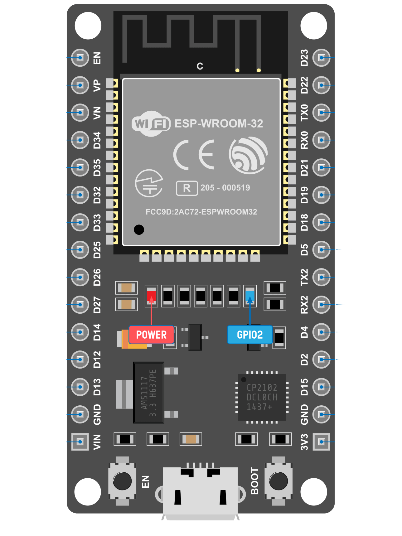
Pin Configuration
The ESP32 has multiple variants, but the following table outlines the general pin configuration for the ESP32-WROOM-32 module:
| Pin Number | Pin Name | Description |
|---|---|---|
| 1 | EN | Enable pin (active high, resets the chip) |
| 2 | GPIO0 | General-purpose I/O, boot mode selection |
| 3 | GPIO1 (TX0) | UART0 transmit pin |
| 4 | GPIO3 (RX0) | UART0 receive pin |
| 5 | GPIO4 | General-purpose I/O, supports PWM, ADC, etc. |
| 6 | GPIO5 | General-purpose I/O, supports PWM, ADC, etc. |
| 7 | 3V3 | 3.3V power supply |
| 8 | GND | Ground |
| 9 | GPIO12 | General-purpose I/O, supports ADC, touch input |
| 10 | GPIO13 | General-purpose I/O, supports ADC, touch input |
| 11 | GPIO14 | General-purpose I/O, supports ADC, touch input |
| 12 | GPIO15 | General-purpose I/O, supports ADC, touch input |
| 13 | GPIO16 | General-purpose I/O |
| 14 | GPIO17 | General-purpose I/O |
Note: The exact pinout may vary depending on the ESP32 module variant. Always refer to the datasheet for your specific module.
Usage Instructions
Using the ESP32 in a Circuit
- Power Supply: Provide a stable 3.3V power supply to the ESP32. Avoid exceeding the maximum voltage of 3.6V to prevent damage.
- Boot Mode: Connect GPIO0 to GND during boot to enable flashing mode. For normal operation, leave GPIO0 unconnected or pull it high.
- Programming: Use a USB-to-serial adapter or a development board with built-in USB connectivity to program the ESP32.
- Connections: Connect peripherals (e.g., sensors, actuators) to the GPIO pins. Ensure the voltage levels are compatible with the ESP32's 3.3V logic.
Best Practices
- Use decoupling capacitors (e.g., 0.1 µF) near the power pins to reduce noise.
- Avoid leaving unused pins floating; pull them high or low as needed.
- Use level shifters if interfacing with 5V logic devices.
- Ensure proper grounding to minimize noise and interference.
Example: Connecting ESP32 to an Arduino UNO
The ESP32 can communicate with an Arduino UNO via UART. Below is an example of how to blink an LED connected to the ESP32 using the Arduino IDE:
Code Example
// Example: Blink an LED on GPIO2 of the ESP32
// Ensure the LED is connected to GPIO2 with a current-limiting resistor.

#define LED_PIN 2  // Define the GPIO pin for the LED

void setup() {
  pinMode(LED_PIN, OUTPUT);  // Set GPIO2 as an output pin
}

void loop() {
  digitalWrite(LED_PIN, HIGH);  // Turn the LED on
  delay(1000);                  // Wait for 1 second
  digitalWrite(LED_PIN, LOW);   // Turn the LED off
  delay(1000);                  // Wait for 1 second
}
Note: Install the ESP32 board package in the Arduino IDE before uploading the code. Go to
File > Preferences, add the ESP32 board URL, and install the package via the Board Manager.
Troubleshooting and FAQs
Common Issues
ESP32 Not Detected by Computer
- Ensure the correct USB driver is installed for your development board.
- Check the USB cable for damage or try a different cable.
Failed to Upload Code
- Verify that the ESP32 is in boot mode (GPIO0 connected to GND).
- Select the correct COM port and board type in the Arduino IDE.
Wi-Fi Connection Issues
- Double-check the SSID and password in your code.
- Ensure the router is within range and supports 2.4 GHz Wi-Fi.
Random Resets or Instability
- Check the power supply for sufficient current (at least 500 mA).
- Add decoupling capacitors to stabilize the power supply.
FAQs
Q: Can the ESP32 operate on 5V?
A: No, the ESP32 operates on 3.3V. Applying 5V to its pins can damage the chip. Use level shifters for 5V devices.
Q: How do I enable Bluetooth on the ESP32?
A: The ESP32 supports both Bluetooth Classic and BLE. Use the BluetoothSerial or BLE libraries in the Arduino IDE to enable Bluetooth functionality.
Q: Can I use the ESP32 for battery-powered applications?
A: Yes, the ESP32 is designed for low-power applications. Use deep sleep mode to minimize power consumption.
Q: What is the maximum range of the ESP32's Wi-Fi?
A: The range depends on environmental factors but typically extends up to 100 meters in open spaces.
By following this documentation, you can effectively integrate the ESP32 into your projects and troubleshoot common issues.