How to Use 6 channel relay module: Examples, Pinouts, and Specs
Introduction
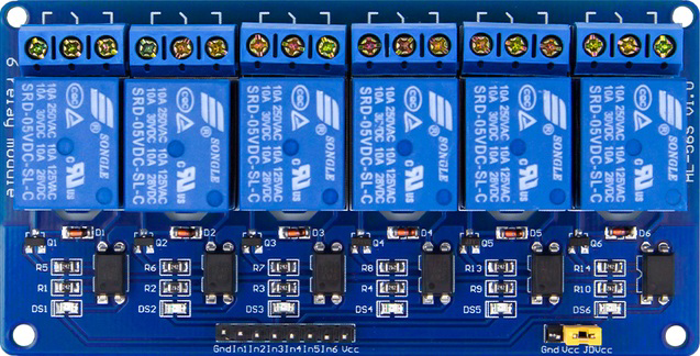
The 6 channel relay module is an electronic component designed to control multiple high-voltage devices using low-voltage signals. Each of the six relays on the module acts as an electrically operated switch, allowing you to control high-power devices such as lights, fans, or appliances with microcontrollers like Arduino, Raspberry Pi, or other control systems.
This module is widely used in home automation, industrial control systems, and robotics, where multiple devices need to be switched on or off independently.
Explore Projects Built with 6 channel relay module


Explore Projects Built with 6 channel relay module
Technical Specifications
- Operating Voltage: 5V DC
- Trigger Voltage: 3.3V to 5V (compatible with most microcontrollers)
- Relay Type: SPDT (Single Pole Double Throw)
- Maximum Load (per relay):
- AC: 250V at 10A
- DC: 30V at 10A
- Optocoupler Isolation: Yes (provides electrical isolation between control and load sides)
- Indicator LEDs: One LED per relay to indicate its state (ON/OFF)
- Dimensions: Varies by manufacturer, typically around 140mm x 50mm x 20mm
Pin Configuration and Descriptions
The 6 channel relay module has two main sections: the control pins and the load terminals.
Control Pins
| Pin Name | Description |
|---|---|
| VCC | Connect to the 5V power supply of the microcontroller or external source. |
| GND | Ground connection. |
| IN1-IN6 | Control pins for each relay. A LOW signal activates the corresponding relay. |
Load Terminals (for each relay)
| Terminal Name | Description |
|---|---|
| COM | Common terminal. Connect to the power source or load. |
| NO | Normally Open terminal. Connect to the load if it should be OFF by default. |
| NC | Normally Closed terminal. Connect to the load if it should be ON by default. |
Usage Instructions
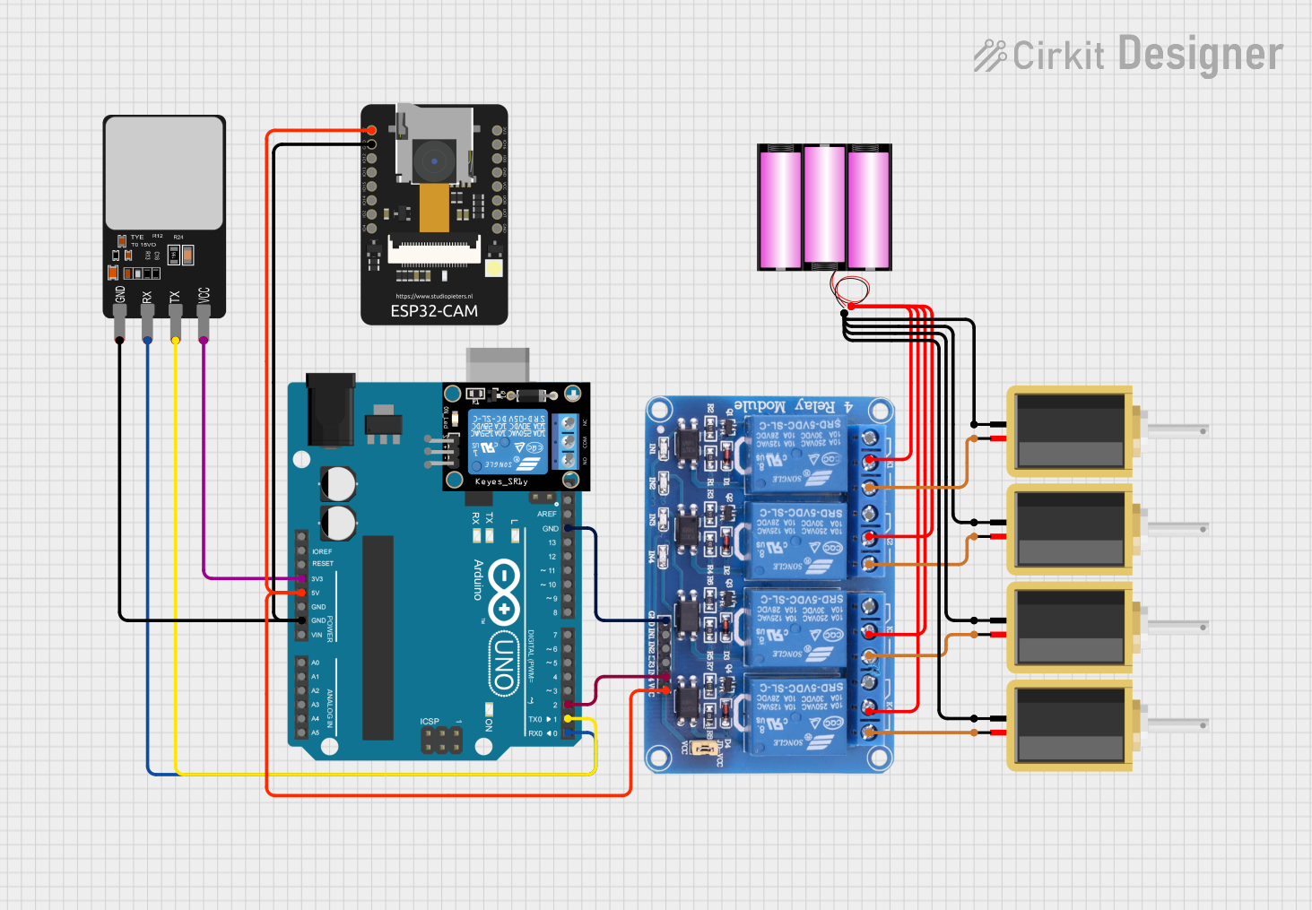
Connecting the Module
- Power the Module: Connect the VCC pin to a 5V power source and the GND pin to ground.
- Control Signals: Connect the IN1-IN6 pins to the digital output pins of your microcontroller. For example, if using an Arduino UNO, connect IN1 to pin 2, IN2 to pin 3, and so on.
- Load Connections:
- Identify the device you want to control (e.g., a light bulb).
- Connect the power source to the COM terminal of the relay.
- Connect the device to either the NO (Normally Open) or NC (Normally Closed) terminal, depending on whether you want the device to be OFF or ON by default.
Example Arduino Code
Below is an example of how to control the 6 channel relay module using an Arduino UNO:
// Define the relay control pins
#define RELAY1 2
#define RELAY2 3
#define RELAY3 4
#define RELAY4 5
#define RELAY5 6
#define RELAY6 7

void setup() {
  // Set relay pins as outputs
  pinMode(RELAY1, OUTPUT);
  pinMode(RELAY2, OUTPUT);
  pinMode(RELAY3, OUTPUT);
  pinMode(RELAY4, OUTPUT);
  pinMode(RELAY5, OUTPUT);
  pinMode(RELAY6, OUTPUT);

  // Initialize all relays to OFF (HIGH state)
  digitalWrite(RELAY1, HIGH);
  digitalWrite(RELAY2, HIGH);
  digitalWrite(RELAY3, HIGH);
  digitalWrite(RELAY4, HIGH);
  digitalWrite(RELAY5, HIGH);
  digitalWrite(RELAY6, HIGH);
}

void loop() {
  // Example: Turn relays ON and OFF sequentially
  digitalWrite(RELAY1, LOW); // Turn ON relay 1
  delay(1000);               // Wait for 1 second
  digitalWrite(RELAY1, HIGH); // Turn OFF relay 1

  digitalWrite(RELAY2, LOW); // Turn ON relay 2
  delay(1000);               // Wait for 1 second
  digitalWrite(RELAY2, HIGH); // Turn OFF relay 2

  // Repeat for other relays...
}
Important Considerations
- Power Supply: Ensure the module is powered with a stable 5V DC supply. Using a power source with insufficient current may cause erratic behavior.
- Isolation: The module includes optocouplers for isolation, but ensure proper grounding between the control and load circuits.
- Load Ratings: Do not exceed the maximum load ratings of the relays to avoid damage or hazards.
- Flyback Diodes: For inductive loads (e.g., motors), use flyback diodes to protect the relays from voltage spikes.
Troubleshooting and FAQs
Common Issues
Relays Not Activating:
- Check if the VCC and GND connections are secure.
- Verify that the control signals (IN1-IN6) are being sent correctly from the microcontroller.
- Ensure the power supply provides sufficient current.
LED Indicators Not Lighting Up:
- Confirm that the module is receiving power.
- Check for loose or broken connections.
Load Not Switching:
- Verify the wiring of the load terminals (COM, NO, NC).
- Ensure the load does not exceed the relay's maximum ratings.
FAQs
Can I use this module with a 3.3V microcontroller?
- Yes, the module is compatible with 3.3V control signals, but ensure the VCC pin is still powered with 5V.
Can I control AC and DC loads simultaneously?
- Yes, as long as each relay's load does not exceed its maximum ratings.
Do I need external components to use this module?
- No additional components are required for basic operation. However, for inductive loads, flyback diodes are recommended.
Can I use fewer than 6 relays?
- Yes, you can use as many relays as needed. Unused relays will remain inactive.
By following this documentation, you can effectively integrate the 6 channel relay module into your projects for reliable and efficient control of multiple devices.