How to Use GY-61: Examples, Pinouts, and Specs
Introduction
The GY-61 is a digital accelerometer module designed to measure acceleration along three axes: X, Y, and Z. It is based on the ADXL345 sensor, which provides high-resolution (13-bit) data for motion detection, tilt sensing, and orientation measurement. The module is compact, lightweight, and easy to integrate into various projects, making it ideal for applications such as robotics, mobile devices, gaming controllers, and wearable technology.
Explore Projects Built with GY-61


Explore Projects Built with GY-61
Common Applications
- Motion detection and gesture recognition
- Tilt and orientation sensing
- Robotics and drone navigation
- Vibration monitoring
- Wearable devices and fitness trackers
Technical Specifications
The GY-61 module is built around the ADXL345 accelerometer sensor. Below are the key technical details:
| Parameter | Specification |
|---|---|
| Operating Voltage | 3.3V to 5V |
| Communication Interface | I2C / SPI |
| Measurement Range | ±2g, ±4g, ±8g, ±16g (configurable) |
| Resolution | 13-bit (4 mg/LSB at ±2g) |
| Operating Temperature | -40°C to +85°C |
| Power Consumption | 40 µA in measurement mode |
| Dimensions | 20mm x 15mm x 3mm |
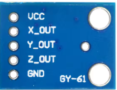
Pin Configuration
The GY-61 module has a 6-pin interface. Below is the pinout description:
| Pin | Name | Description |
|---|---|---|
| 1 | VCC | Power supply input (3.3V to 5V) |
| 2 | GND | Ground connection |
| 3 | SCL | Serial Clock Line for I2C communication |
| 4 | SDA | Serial Data Line for I2C communication |
| 5 | CS | Chip Select (used for SPI communication; connect to GND for I2C mode) |
| 6 | INT | Interrupt pin (used for motion detection or data-ready signals) |
Usage Instructions
Connecting the GY-61 to an Arduino UNO
The GY-61 can be easily interfaced with an Arduino UNO using the I2C protocol. Below is the wiring guide:
| GY-61 Pin | Arduino UNO Pin |
|---|---|
| VCC | 5V |
| GND | GND |
| SCL | A5 (SCL) |
| SDA | A4 (SDA) |
| CS | GND |
| INT | Not connected (optional) |
Sample Arduino Code
The following code demonstrates how to read acceleration data from the GY-61 module using the I2C interface:
#include <Wire.h>

// ADXL345 I2C address
#define ADXL345_ADDRESS 0x53

// Register addresses
#define POWER_CTL 0x2D
#define DATA_FORMAT 0x31
#define DATAX0 0x32

void setup() {
  Wire.begin(); // Initialize I2C communication
  Serial.begin(9600); // Initialize serial communication for debugging

  // Initialize the ADXL345
  Wire.beginTransmission(ADXL345_ADDRESS);
  Wire.write(POWER_CTL); // Access POWER_CTL register
  Wire.write(0x08); // Set measurement mode
  Wire.endTransmission();

  Wire.beginTransmission(ADXL345_ADDRESS);
  Wire.write(DATA_FORMAT); // Access DATA_FORMAT register
  Wire.write(0x08); // Set range to ±2g
  Wire.endTransmission();

  Serial.println("GY-61 initialized successfully!");
}

void loop() {
  int16_t x, y, z;

  // Request 6 bytes of data starting from DATAX0
  Wire.beginTransmission(ADXL345_ADDRESS);
  Wire.write(DATAX0);
  Wire.endTransmission(false);
  Wire.requestFrom(ADXL345_ADDRESS, 6);

  // Read acceleration data
  if (Wire.available() == 6) {
    x = (Wire.read() | (Wire.read() << 8)); // Combine low and high bytes for X-axis
    y = (Wire.read() | (Wire.read() << 8)); // Combine low and high bytes for Y-axis
    z = (Wire.read() | (Wire.read() << 8)); // Combine low and high bytes for Z-axis
  }

  // Print acceleration values
  Serial.print("X: ");
  Serial.print(x);
  Serial.print(" Y: ");
  Serial.print(y);
  Serial.print(" Z: ");
  Serial.println(z);

  delay(500); // Delay for readability
}
Important Considerations
- Power Supply: Ensure the module is powered within the specified voltage range (3.3V to 5V).
- I2C Pull-Up Resistors: If the I2C lines (SCL and SDA) are not already pulled up, add 4.7kΩ resistors to VCC.
- Interrupt Pin: The INT pin can be used for advanced features like motion detection but is optional for basic usage.
- Orientation: Mount the module securely to avoid vibrations or misalignment that could affect readings.
Troubleshooting and FAQs
Common Issues
No Data Output
- Cause: Incorrect wiring or loose connections.
- Solution: Double-check the wiring and ensure all connections are secure.
Incorrect or Unstable Readings
- Cause: Excessive noise or vibrations.
- Solution: Mount the module on a stable surface and use software filtering if needed.
I2C Communication Failure
- Cause: Incorrect I2C address or missing pull-up resistors.
- Solution: Verify the I2C address (default is 0x53) and add 4.7kΩ pull-up resistors to SCL and SDA lines.
FAQs
Can the GY-61 be used with 3.3V microcontrollers?
- Yes, the module supports both 3.3V and 5V logic levels.
How do I change the measurement range?
- Modify the
DATA_FORMATregister in the code to set the desired range (±2g, ±4g, ±8g, or ±16g).
- Modify the
What is the maximum sampling rate of the GY-61?
- The ADXL345 sensor supports a maximum output data rate of 3200 Hz.
By following this documentation, you can effectively integrate the GY-61 accelerometer module into your projects for reliable motion and orientation sensing.