How to Use USB: Examples, Pinouts, and Specs
Introduction
The Universal Serial Bus (USB) is a widely adopted standard for connecting peripheral devices to computers and power sources. It facilitates both data transfer and electrical power supply, making it an essential component in modern electronics. USB is used in a variety of applications, including charging mobile devices, connecting external storage, interfacing with input devices (e.g., keyboards and mice), and enabling communication between embedded systems.
Common applications and use cases:
- Charging and powering devices such as smartphones, tablets, and wearables.
- Data transfer between computers and external devices like flash drives or hard drives.
- Communication between microcontrollers and computers for programming or data logging.
- Connecting peripherals such as printers, webcams, and game controllers.
Explore Projects Built with USB


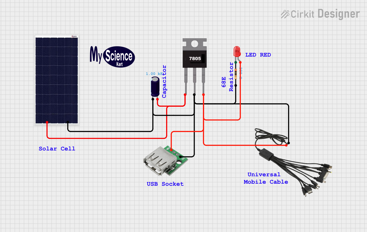
Explore Projects Built with USB
Technical Specifications
The USB standard has evolved over time, with multiple versions offering varying data transfer rates and power capabilities. Below are the key specifications for USB:
| Specification | USB 2.0 | USB 3.0 | USB 3.1/3.2 | USB4 |
|---|---|---|---|---|
| Data Transfer Rate | 480 Mbps | 5 Gbps | Up to 20 Gbps | Up to 40 Gbps |
| Power Delivery (Max) | 2.5 W (5V, 500mA) | 4.5 W (5V, 900mA) | Up to 100 W | Up to 100 W |
| Connector Types | USB-A, USB-B, Mini-USB, Micro-USB | USB-A, USB-B, USB-C | USB-C | USB-C |
Pin Configuration and Descriptions
The pin configuration varies depending on the USB connector type. Below is the pinout for the most common USB connectors:
USB Type-A (Standard)
| Pin | Name | Description |
|---|---|---|
| 1 | VBUS | +5V Power Supply |
| 2 | D- | Data Line (Negative) |
| 3 | D+ | Data Line (Positive) |
| 4 | GND | Ground |
USB Type-C
| Pin | Name | Description |
|---|---|---|
| A1, B1 | GND | Ground |
| A4, B4 | VBUS | +5V Power Supply |
| A6, B6 | D- | Data Line (Negative) |
| A7, B7 | D+ | Data Line (Positive) |
| A5, B5 | CC | Configuration Channel for Power/Role Negotiation |
| A8, B8 | SBU1, SBU2 | Sideband Use |
Usage Instructions
How to Use USB in a Circuit
- Power Supply: USB can provide a regulated 5V power supply. Ensure your circuit does not draw more current than the USB port can supply (e.g., 500mA for USB 2.0).
- Data Communication: Connect the D+ and D- lines to the appropriate data pins of your microcontroller or device. Use pull-up or pull-down resistors as required by the USB specification.
- Connector Selection: Choose the appropriate USB connector type (e.g., USB-A, USB-C) based on your application and device compatibility.
Important Considerations and Best Practices
- Power Management: If your circuit requires more power than the USB port can provide, consider using an external power source or USB Power Delivery (USB PD) for higher power requirements.
- Signal Integrity: Use short, shielded cables to minimize noise and signal degradation, especially for high-speed USB versions.
- ESD Protection: Add ESD protection diodes on the data lines to protect against electrostatic discharge.
- USB Compliance: Follow USB standards to ensure compatibility with other devices.
Example: Connecting USB to an Arduino UNO
The Arduino UNO can communicate with a computer via USB for programming and serial communication. Below is an example of Arduino code to send data over USB:
// This example sends "Hello, USB!" to the serial monitor via USB
void setup() {
  Serial.begin(9600); // Initialize serial communication at 9600 baud
}

void loop() {
  Serial.println("Hello, USB!"); // Send a message over USB
  delay(1000); // Wait for 1 second before sending the next message
}
Troubleshooting and FAQs
Common Issues
Device Not Recognized:
- Ensure the USB cable is properly connected and not damaged.
- Verify that the device drivers are installed on the computer.
- Check the power supply to ensure the device is receiving sufficient power.
Slow Data Transfer:
- Use a USB cable and port that support the required USB version (e.g., USB 3.0 for higher speeds).
- Avoid using long or unshielded cables that can degrade signal quality.
Overcurrent Protection Triggered:
- Ensure your circuit does not draw more current than the USB port's maximum rating.
- Use a powered USB hub if additional current is required.
FAQs
Q: Can I use a USB 3.0 device with a USB 2.0 port?
A: Yes, USB 3.0 is backward compatible with USB 2.0, but the data transfer rate will be limited to USB 2.0 speeds.
Q: What is USB Power Delivery (USB PD)?
A: USB PD is a protocol that allows devices to negotiate higher power levels (up to 100W) over a USB-C connection.
Q: How do I identify the USB version of a port or cable?
A: USB 3.0 ports are often marked with a blue color, while USB-C cables and ports may have "SS" (SuperSpeed) or "PD" (Power Delivery) labels. Always check the product specifications for confirmation.