How to Use TENSTAR T‑Display ESP32‑D0WD: Examples, Pinouts, and Specs
Introduction
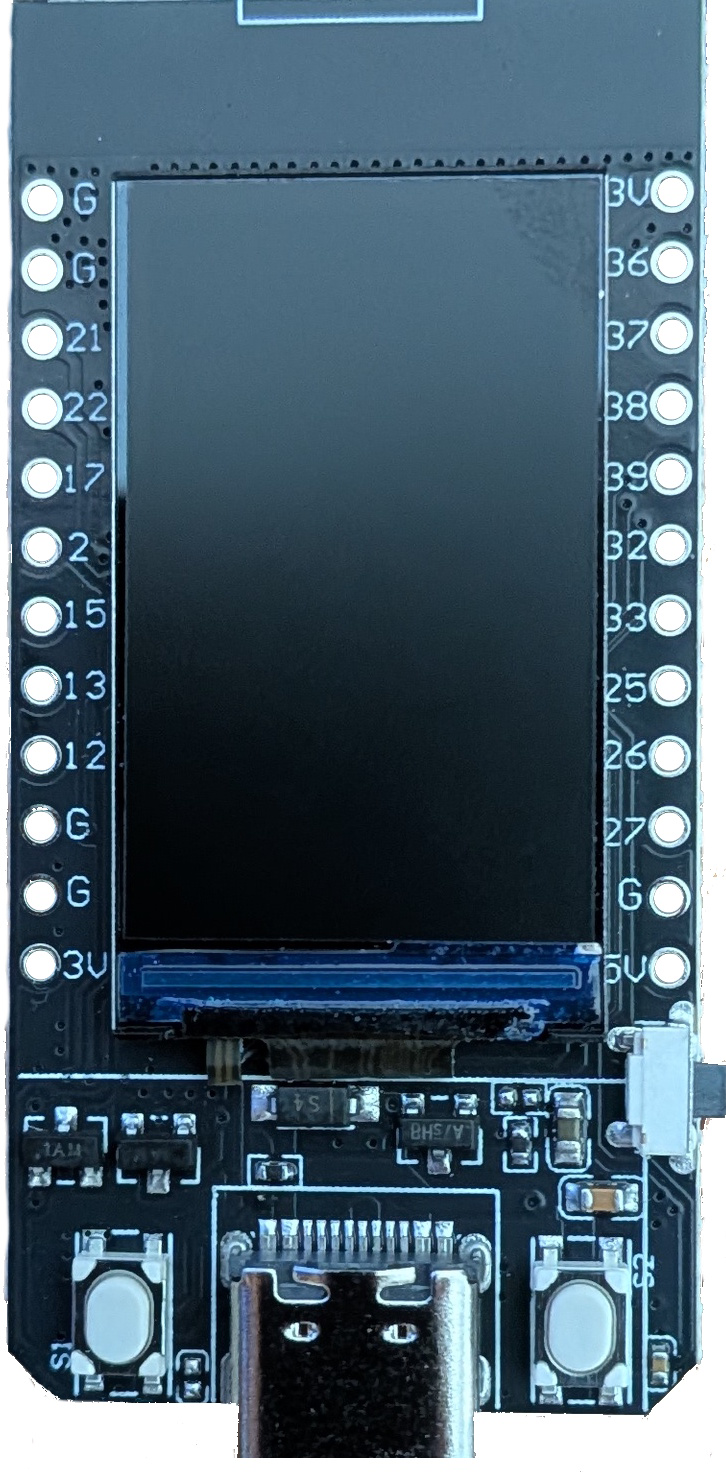
The TENSTAR T‑Display ESP32‑D0WD is a compact and versatile development board designed for IoT, embedded systems, and prototyping applications. It features the powerful ESP32 microcontroller, which integrates dual-core processing, Wi-Fi, and Bluetooth capabilities. Additionally, the board includes a built-in 1.14-inch color TFT display, making it ideal for projects requiring visual output or user interaction.
Explore Projects Built with TENSTAR T‑Display ESP32‑D0WD

Explore Projects Built with TENSTAR T‑Display ESP32‑D0WD
Common Applications
- IoT devices and smart home systems
- Wearable technology
- Data logging and monitoring with visual feedback
- Prototyping and educational projects
- Wireless communication and control systems
Technical Specifications
Key Technical Details
| Parameter | Specification |
|---|---|
| Microcontroller | ESP32-D0WD (dual-core, 32-bit Xtensa LX6 CPU) |
| Clock Speed | Up to 240 MHz |
| Flash Memory | 4 MB (SPI Flash) |
| SRAM | 520 KB |
| Wireless Connectivity | Wi-Fi 802.11 b/g/n, Bluetooth v4.2 (BLE + BR/EDR) |
| Display | 1.14-inch TFT LCD, 135x240 resolution, ST7789 driver |
| Operating Voltage | 3.3V |
| Input Voltage Range | 5V (via USB-C) |
| GPIO Pins | 14 (including ADC, DAC, I2C, SPI, UART, PWM) |
| Power Supply Interface | USB-C |
| Dimensions | 51mm x 25mm |
Pin Configuration and Descriptions
| Pin Name | Pin Number | Description |
|---|---|---|
| GND | Multiple | Ground pin |
| 3V3 | Multiple | 3.3V power output |
| GPIO0 | 0 | General-purpose I/O, boot mode selection |
| GPIO2 | 2 | General-purpose I/O, supports ADC and PWM |
| GPIO4 | 4 | General-purpose I/O, supports ADC and PWM |
| GPIO5 | 5 | General-purpose I/O, supports ADC and PWM |
| GPIO12 | 12 | General-purpose I/O, supports ADC and PWM |
| GPIO13 | 13 | General-purpose I/O, supports ADC and PWM |
| GPIO14 | 14 | General-purpose I/O, supports ADC and PWM |
| GPIO15 | 15 | General-purpose I/O, supports ADC and PWM |
| GPIO16 | 16 | General-purpose I/O, supports ADC and PWM |
| GPIO17 | 17 | General-purpose I/O, supports ADC and PWM |
| RX | 3 | UART receive pin |
| TX | 1 | UART transmit pin |
Usage Instructions
How to Use the Component in a Circuit
- Powering the Board: Connect the board to a 5V power source using the USB-C port. The onboard voltage regulator will step down the voltage to 3.3V for the ESP32.
- Programming: Use the Arduino IDE or ESP-IDF to program the ESP32. Ensure the correct board and port are selected in the IDE.
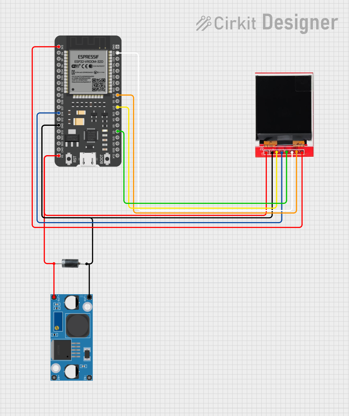
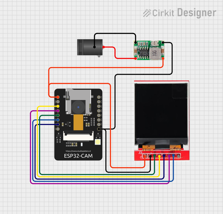
- Connecting Peripherals: Use the GPIO pins to connect sensors, actuators, or other peripherals. Refer to the pin configuration table for supported functionalities.
- Using the Display: The onboard 1.14-inch TFT display can be controlled using the ST7789 driver library. Install the
TFT_eSPIlibrary in the Arduino IDE for easy integration.
Important Considerations and Best Practices
- Voltage Levels: Ensure all connected peripherals operate at 3.3V logic levels to avoid damaging the ESP32.
- Boot Mode: GPIO0 is used for boot mode selection. Avoid pulling it high during startup unless necessary.
- Heat Management: The ESP32 can get warm during operation. Ensure proper ventilation if used in enclosed spaces.
- Display Initialization: Always initialize the display in your code before attempting to draw graphics or text.
Example Code for Arduino UNO
Below is an example of how to display text on the onboard TFT screen using the TFT_eSPI library:
#include <TFT_eSPI.h> // Include the TFT library

TFT_eSPI tft = TFT_eSPI(); // Create an instance of the display

void setup() {
  tft.init(); // Initialize the display
  tft.setRotation(1); // Set display orientation
  tft.fillScreen(TFT_BLACK); // Clear the screen with black color

  tft.setTextColor(TFT_WHITE, TFT_BLACK); // Set text color and background
  tft.setTextSize(2); // Set text size

  tft.setCursor(10, 10); // Set cursor position
  tft.println("Hello, World!"); // Print text to the display
}

void loop() {
  // No actions in the loop for this example
}
Troubleshooting and FAQs
Common Issues and Solutions
The board does not power on:
- Ensure the USB-C cable is properly connected and functional.
- Verify the power source provides sufficient current (at least 500mA).
Unable to upload code:
- Check that the correct board and port are selected in the Arduino IDE.
- Ensure the USB driver for the ESP32 is installed on your computer.
- Press and hold the BOOT button while uploading the code.
Display does not work:
- Verify that the
TFT_eSPIlibrary is installed and configured correctly. - Ensure the display initialization code is included in your sketch.
- Check the wiring if using an external display.
- Verify that the
Wi-Fi or Bluetooth not working:
- Ensure the correct credentials or pairing settings are used in your code.
- Check for interference from other devices or networks.
FAQs
Q: Can I power the board using a battery?
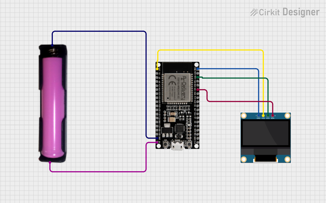
A: Yes, you can use a 3.7V LiPo battery connected to the 3V3 pin, but ensure proper voltage regulation.
Q: What is the maximum current draw of the board?
A: The board typically draws around 200mA during operation but can peak up to 500mA when using Wi-Fi or Bluetooth.
Q: Can I use the board with MicroPython?
A: Yes, the ESP32 is compatible with MicroPython. You can flash the MicroPython firmware and use it for development.
Q: Is the display removable?
A: No, the display is soldered onto the board and is not designed to be removed.
This documentation provides a comprehensive guide to using the TENSTAR T‑Display ESP32‑D0WD effectively in your projects.