How to Use Adafruit I2S Mic breakout (SPH0645): Examples, Pinouts, and Specs
Adafruit I2S Microphone Breakout (SPH0645) Documentation
1. Introduction
The Adafruit I2S Microphone Breakout (SPH0645) is a compact, high-performance digital microphone module designed for capturing high-quality audio. It utilizes the I2S (Inter-IC Sound) interface for transmitting audio data, making it an excellent choice for projects requiring precise and efficient sound capture. Unlike analog microphones, the SPH0645 outputs digital audio data, reducing noise and improving signal quality.
This breakout board is ideal for applications such as:
- Voice recognition systems
- Audio recording and processing
- Sound level monitoring
- IoT devices with audio input
- DIY smart assistants and home automation projects
The SPH0645 is compatible with microcontrollers like the Arduino UNO, Raspberry Pi, and other platforms that support I2S communication.
2. Technical Specifications
Key Technical Details
| Parameter | Value |
|---|---|
| Microphone Type | Digital MEMS Microphone |
| Interface | I2S (Inter-IC Sound) |
| Supply Voltage (VDD) | 1.8V to 3.3V |
| Current Consumption | ~1.4 mA (typical) |
| Frequency Response | 50 Hz to 15 kHz |
| Signal-to-Noise Ratio | 65 dB |
| Sensitivity | -26 dBFS ±3 dB |
| Output Format | 24-bit PCM (Pulse Code Modulation) |
| Dimensions | 15.2mm x 17.7mm x 1.5mm |
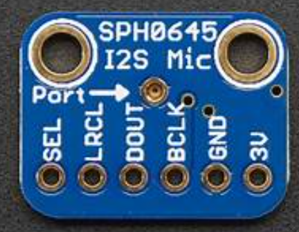
Pin Configuration and Descriptions
| Pin Name | Pin Number | Description |
|---|---|---|
| 3V | 1 | Power supply input (1.8V to 3.3V). Connect to 3.3V on your microcontroller. |
| GND | 2 | Ground connection. Connect to the ground of your circuit. |
| BCLK | 3 | Bit Clock input for I2S communication. |
| DOUT | 4 | Data Output. Transmits the digital audio data in I2S format. |
| LRCLK | 5 | Left/Right Clock input for I2S communication. Determines left or right channel. |
3. Usage Instructions
Connecting the SPH0645 to an Arduino UNO
The SPH0645 requires an I2S interface, which is not natively supported by the Arduino UNO. However, it can be used with other Arduino boards like the Arduino Nano 33 BLE Sense or Arduino Zero, which have I2S capabilities. For demonstration purposes, we will use the Arduino Nano 33 BLE Sense.
Wiring Diagram
| SPH0645 Pin | Arduino Pin |
|---|---|
| 3V | 3.3V |
| GND | GND |
| BCLK | D3 (I2S Bit Clock) |
| DOUT | D4 (I2S Data Input) |
| LRCLK | D5 (I2S Word Select) |
Arduino Code Example
Below is an example code to capture audio data from the SPH0645 using the Arduino I2S library:
#include <I2S.h> // Include the I2S library for audio data handling

void setup() {
  Serial.begin(115200); // Initialize serial communication for debugging
  while (!Serial);      // Wait for the serial monitor to open

  // Start the I2S interface in receive mode
  if (!I2S.begin(I2S_PHILIPS_MODE, 44100, 32)) {
    Serial.println("Failed to initialize I2S!");
    while (1); // Halt the program if I2S initialization fails
  }

  Serial.println("I2S Microphone Initialized!");
}

void loop() {
  int sample = 0;

  // Check if audio data is available
  if (I2S.available()) {
    sample = I2S.read(); // Read a 32-bit audio sample from the microphone

    // Print the audio sample to the serial monitor
    Serial.println(sample);
  }
}
Important Considerations and Best Practices
- Power Supply: Ensure the SPH0645 is powered with a stable voltage between 1.8V and 3.3V. Do not exceed 3.3V.
- I2S Compatibility: Verify that your microcontroller supports I2S communication. The Arduino UNO does not natively support I2S.
- Clock Signals: The SPH0645 requires both BCLK (Bit Clock) and LRCLK (Left/Right Clock) signals to function correctly.
- Noise Reduction: Use short, shielded wires for connections to minimize noise and interference.
- Sampling Rate: The SPH0645 supports a sampling rate of up to 48 kHz. Ensure your microcontroller is configured accordingly.
4. Troubleshooting and FAQs
Common Issues and Solutions
| Issue | Possible Cause | Solution |
|---|---|---|
| No audio data is received | Incorrect wiring or pin connections | Double-check the wiring and ensure all connections match the pinout table. |
| I2S initialization fails | Microcontroller does not support I2S | Use a microcontroller with I2S support, such as the Arduino Nano 33 BLE. |
| Audio data is noisy or distorted | Power supply noise or long wires | Use a stable power source and keep wires short to reduce interference. |
| Low audio sensitivity | Incorrect microphone orientation | Ensure the microphone's sound port is unobstructed and facing the sound source. |
| Sampling rate mismatch | Microcontroller and SPH0645 not synchronized | Set the correct sampling rate in your code (e.g., 44.1 kHz or 48 kHz). |
Frequently Asked Questions (FAQs)
Can I use the SPH0645 with the Arduino UNO?
- The Arduino UNO does not natively support I2S. Use a board like the Arduino Nano 33 BLE or Arduino Zero.
What is the maximum sampling rate supported by the SPH0645?
- The SPH0645 supports sampling rates up to 48 kHz.
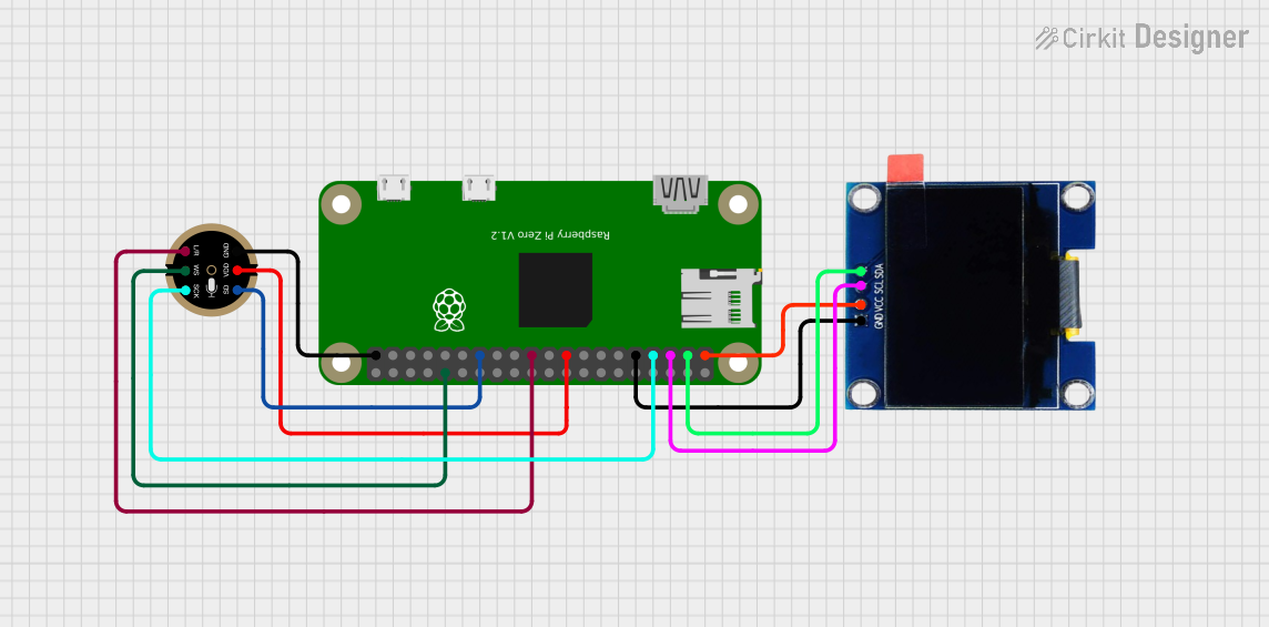
Can I use the SPH0645 with a Raspberry Pi?
- Yes, the SPH0645 is fully compatible with the Raspberry Pi, which has native I2S support.
How do I reduce noise in my audio recordings?
- Use short, shielded wires for connections, and ensure the microphone is powered by a clean, stable voltage source.
What is the difference between BCLK and LRCLK?
- BCLK (Bit Clock): Synchronizes the data transfer between the microphone and the microcontroller.
- LRCLK (Left/Right Clock): Indicates whether the current audio data corresponds to the left or right audio channel.
This documentation provides a comprehensive guide to using the Adafruit I2S Microphone Breakout (SPH0645). Whether you're a beginner or an experienced user, this guide will help you integrate the SPH0645 into your next audio project with ease.
Explore Projects Built with Adafruit I2S Mic breakout (SPH0645)
Explore Projects Built with Adafruit I2S Mic breakout (SPH0645)