
How to Use SCT-013 Current Sensor: Examples, Pinouts, and Specs
 Design with SCT-013 Current Sensor in Cirkit Designer
Introduction
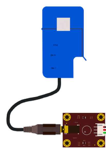
The SCT-013 is a non-invasive current sensor designed to measure alternating current (AC) by clamping around a conductor. Manufactured by Arduino under the part ID Sen0211 with SCT-013, this sensor outputs a voltage proportional to the current flowing through the conductor. It is widely used in energy monitoring systems, home automation, and industrial applications for tracking power consumption and optimizing energy usage.
Explore Projects Built with SCT-013 Current Sensor
 Open Project in Cirkit Designer
 Open Project in Cirkit Designer
 Open Project in Cirkit Designer
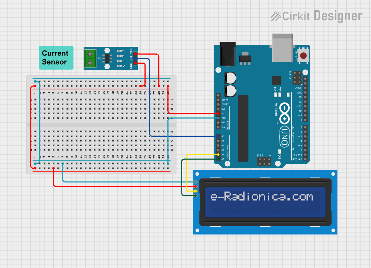 Open Project in Cirkit Designer
Explore Projects Built with SCT-013 Current Sensor
Open Project in Cirkit DesignerOpen Project in Cirkit DesignerOpen Project in Cirkit DesignerOpen Project in Cirkit DesignerCommon Applications:
- Energy monitoring in residential and industrial environments
- Smart home automation systems
- Power consumption analysis for appliances
- Renewable energy systems (e.g., solar or wind energy monitoring)
- Overcurrent detection in electrical systems
Technical Specifications
Key Technical Details:
- Model: SCT-013
- Manufacturer Part ID: Sen0211
- Input Current Range: 0–100 A AC (varies by model variant)
- Output Signal: Voltage (proportional to current)
- Accuracy: ±1% (typical)
- Output Connector: 3.5 mm audio jack
- Core Material: Ferrite
- Operating Temperature: -25°C to +70°C
- Dielectric Strength: 6000 V AC (1 minute)
- Cable Length: 1 meter (standard)
Pin Configuration and Descriptions:
The SCT-013 sensor uses a 3.5 mm audio jack for its output. The pinout is as follows:
| Pin | Description |
|---|---|
| Tip | Signal output (voltage proportional to AC current) |
| Ring | Ground |
| Sleeve | Shield (optional, for noise reduction) |
Usage Instructions
How to Use the SCT-013 in a Circuit:
Connect the Sensor:
- Clamp the SCT-013 sensor around the live or neutral wire of the AC circuit you want to monitor. Ensure the wire is insulated and the clamp is securely closed.
- Plug the 3.5 mm audio jack into the input of your circuit or microcontroller interface.
Voltage Divider Circuit:
- The SCT-013 outputs an AC voltage proportional to the current. To interface with a microcontroller (e.g., Arduino UNO), you need a voltage divider circuit to bias the signal to the mid-point of the ADC range (typically 2.5 V for a 5 V system).
- Use two resistors of equal value (e.g., 10 kΩ) to create the voltage divider.
Connect to Arduino UNO:
- Connect the signal output (tip) to an analog input pin (e.g., A0) on the Arduino.
- Connect the ground (ring) to the Arduino's GND pin.
Calibration:
- The output voltage of the SCT-013 is proportional to the current, but calibration is required to convert the ADC readings into actual current values. Use a known load to determine the calibration constant.
Example Arduino Code:
// Example code for using the SCT-013 current sensor with Arduino UNO
// This code reads the sensor output and calculates the RMS current.

const int sensorPin = A0; // Analog pin connected to SCT-013 signal output
const float calibrationFactor = 100.0; // Adjust based on your sensor model
const int numSamples = 1000; // Number of samples for RMS calculation

void setup() {
  Serial.begin(9600); // Initialize serial communication
}

void loop() {
  float sum = 0; // Variable to store the sum of squared readings

  // Take multiple samples to calculate RMS
  for (int i = 0; i < numSamples; i++) {
    int rawValue = analogRead(sensorPin); // Read the analog value
    float voltage = (rawValue / 1023.0) * 5.0; // Convert to voltage
    float current = (voltage - 2.5) * calibrationFactor;
    // Subtract 2.5 to remove bias, then scale by calibration factor
    sum += current * current; // Square the current and add to sum
    delay(1); // Small delay between samples
  }

  float rmsCurrent = sqrt(sum / numSamples); // Calculate RMS current
  Serial.print("RMS Current: ");
  Serial.print(rmsCurrent);
  Serial.println(" A"); // Print current in amperes

  delay(1000); // Wait 1 second before next reading
}
Important Considerations:
- Safety: Ensure the conductor being measured is insulated and the sensor is clamped securely. Do not use the sensor on bare wires.
- Calibration: The calibration factor depends on the specific SCT-013 model and the burden resistor used. Refer to the datasheet for precise values.
- Noise Reduction: Use shielded cables and proper grounding to minimize noise in the output signal.
- Burden Resistor: Some SCT-013 models include an internal burden resistor, while others require an external one. Verify your model's configuration before use.
Troubleshooting and FAQs
Common Issues:
No Output Signal:
- Ensure the sensor is clamped around a live or neutral wire carrying current.
- Verify the 3.5 mm jack is securely connected to the circuit.
Inaccurate Readings:
- Check the calibration factor and ensure it matches your sensor model.
- Verify the burden resistor value and connections.
High Noise in Output:
- Use shielded cables and ensure proper grounding.
- Avoid running the sensor cable parallel to high-voltage lines.
Arduino ADC Saturation:
- Ensure the voltage divider circuit biases the signal correctly within the ADC range.
- Check for excessive current that may cause the sensor to output a voltage beyond the ADC range.
FAQs:
Q1: Can the SCT-013 measure DC current?
A1: No, the SCT-013 is designed for AC current measurement only. It cannot measure DC current.
Q2: What is the maximum current the SCT-013 can measure?
A2: The maximum current depends on the specific model variant. Common models measure up to 30 A, 50 A, or 100 A.
Q3: Can I use the SCT-013 with a Raspberry Pi?
A3: Yes, but since the Raspberry Pi lacks an analog-to-digital converter (ADC), you will need an external ADC module (e.g., MCP3008) to interface the SCT-013.
Q4: How do I know if my SCT-013 has an internal burden resistor?
A4: Check the model number printed on the sensor or refer to the datasheet. Models with an internal burden resistor typically have a voltage output specification (e.g., 1 V or 0.333 V).
By following this documentation, you can effectively integrate the SCT-013 current sensor into your projects for accurate and reliable AC current measurement.