How to Use SD: Examples, Pinouts, and Specs
Introduction
- A Secure Digital (SD) card is a non-volatile memory card used for storing data in portable devices such as cameras, smartphones, and tablets. It provides a compact and removable storage solution with varying capacities and speeds.
- Common applications include:
- Storing photos, videos, and audio files in cameras and smartphones.
- Expanding storage for embedded systems and microcontrollers.
- Data logging in IoT devices and industrial applications.
- Bootable storage for single-board computers like Raspberry Pi.
Explore Projects Built with SD


Explore Projects Built with SD
Technical Specifications
- Form Factors: Standard SD, miniSD, microSD.
- Capacities: Ranges from 2 MB to 2 TB (SD, SDHC, SDXC, SDUC standards).
- Speed Classes:
- Class 2, 4, 6, 10 (Standard Speed Classes).
- UHS-I, UHS-II, UHS-III (Ultra High-Speed Classes).
- Video Speed Classes (V6, V10, V30, V60, V90).
- Voltage: 2.7V to 3.6V (typical operating range).
- Interface: SPI (Serial Peripheral Interface) or SD bus mode.
- File System: FAT12, FAT16, FAT32, exFAT (depending on capacity).
Pin Configuration and Descriptions
The SD card has 9 pins in its standard form factor. Below is the pinout and description:
| Pin Number | Pin Name | Description |
|---|---|---|
| 1 | DAT2 | Data Line 2 (not used in SPI mode) |
| 2 | CD/DAT3 | Card Detect/Data Line 3 |
| 3 | CMD | Command/Response Line |
| 4 | VDD | Power Supply (2.7V to 3.6V) |
| 5 | CLK | Clock Signal |
| 6 | VSS | Ground |
| 7 | DAT0 | Data Line 0 |
| 8 | DAT1 | Data Line 1 |
| 9 | NC | Not Connected |
For microSD cards, the pinout is similar but in a smaller form factor.
Usage Instructions
How to Use the SD Card in a Circuit
Connection:
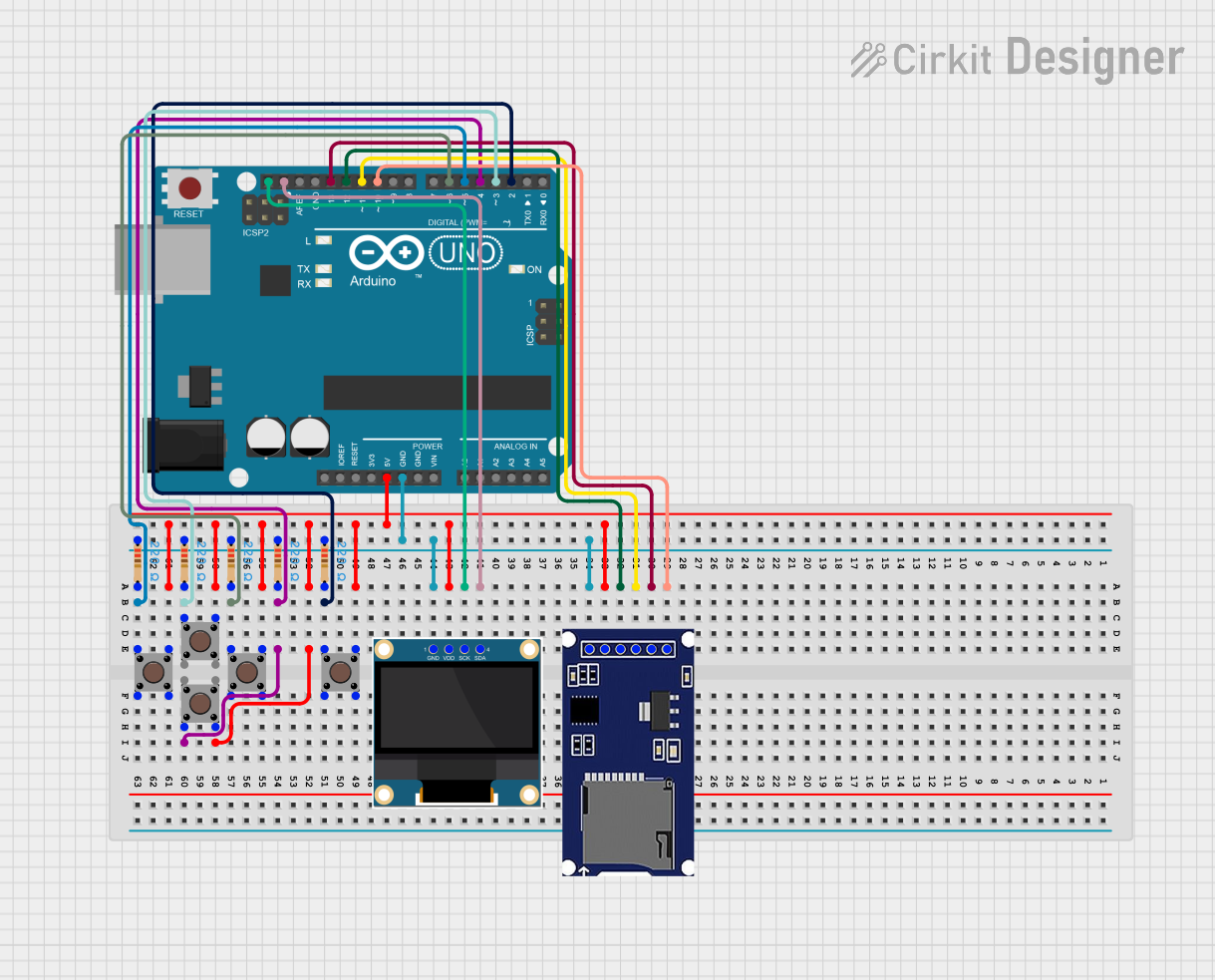
- Use an SD card module or breakout board to simplify connections.
- Connect the SD card to a microcontroller using SPI or SD bus mode.
- Ensure proper voltage regulation if the microcontroller operates at 5V (use a level shifter if needed).
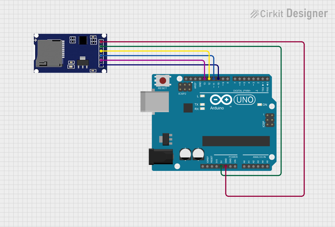
Wiring Example (SPI Mode):
- Connect the SD card pins to the microcontroller as follows:
CLKto SPI Clock (SCK).CMDto SPI MOSI (Master Out Slave In).DAT0to SPI MISO (Master In Slave Out).VDDto 3.3V power supply.VSSto Ground.
- Connect the SD card pins to the microcontroller as follows:
Software Setup:
- Use an SD card library (e.g., Arduino SD library) to initialize and communicate with the card.
- Format the SD card with a compatible file system (e.g., FAT32).
Arduino UNO Example Code
#include <SPI.h>
#include <SD.h>

// Define the chip select pin for the SD card module
const int chipSelect = 4;

void setup() {
  Serial.begin(9600);
  while (!Serial) {
    // Wait for the serial port to connect (for native USB boards)
  }

  Serial.println("Initializing SD card...");

  // Initialize the SD card
  if (!SD.begin(chipSelect)) {
    Serial.println("Card failed, or not present");
    // Stop further execution if the card is not detected
    return;
  }
  Serial.println("Card initialized successfully!");

  // Create or open a file on the SD card
  File dataFile = SD.open("example.txt", FILE_WRITE);
  if (dataFile) {
    dataFile.println("Hello, SD card!");
    dataFile.close(); // Close the file to save changes
    Serial.println("Data written to file.");
  } else {
    Serial.println("Error opening file.");
  }
}

void loop() {
  // Nothing to do here
}
Important Considerations and Best Practices
- Always use a level shifter or voltage regulator when interfacing with 5V systems.
- Format the SD card using official tools or operating system utilities to ensure compatibility.
- Avoid removing the SD card while the system is powered on to prevent data corruption.
- Use proper pull-up resistors on the SPI lines if required by your circuit.
Troubleshooting and FAQs
Common Issues
SD Card Not Detected:
- Ensure proper wiring and check for loose connections.
- Verify that the SD card is formatted with a supported file system.
- Check the voltage levels and ensure compatibility with the SD card.
File Write/Read Errors:
- Ensure sufficient free space on the SD card.
- Verify that the file name and path are correct.
- Check for proper initialization in the code.
Slow Performance:
- Use an SD card with a higher speed class for better performance.
- Optimize the code to reduce unnecessary read/write operations.
FAQs
Q: Can I use a microSD card in place of a standard SD card?
A: Yes, with an appropriate adapter, microSD cards can be used in standard SD card slots.Q: What is the maximum capacity supported by an Arduino UNO?
A: The Arduino SD library supports FAT16 and FAT32 file systems, which means it can handle SD cards up to 32 GB.Q: How do I safely remove the SD card from my circuit?
A: Always power down the system or ensure no ongoing read/write operations before removing the SD card to prevent data corruption.Q: Can I use the SD card for real-time data logging?
A: Yes, but ensure the SD card has a high write speed and optimize your code to minimize delays.