
How to Use IO Expansion Shield for Arduino Nano: Examples, Pinouts, and Specs
 Design with IO Expansion Shield for Arduino Nano in Cirkit Designer
Introduction
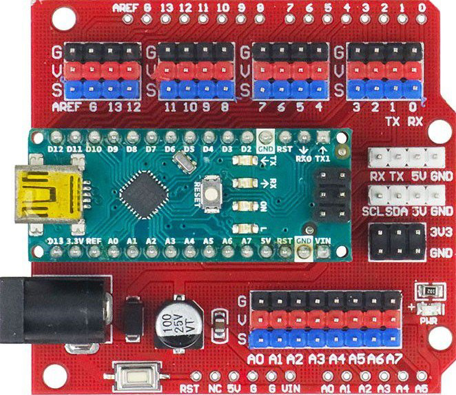
The IO Expansion Shield for Arduino Nano is a versatile add-on board designed to enhance the functionality of the Arduino Nano. By providing additional input/output (I/O) pins, this shield allows users to connect and control a greater number of sensors, actuators, and other peripheral devices. It simplifies prototyping and development by offering easy-to-access pin headers, onboard power management, and compatibility with various modules.
Explore Projects Built with IO Expansion Shield for Arduino Nano
 Open Project in Cirkit Designer
 Open Project in Cirkit Designer
 Open Project in Cirkit Designer
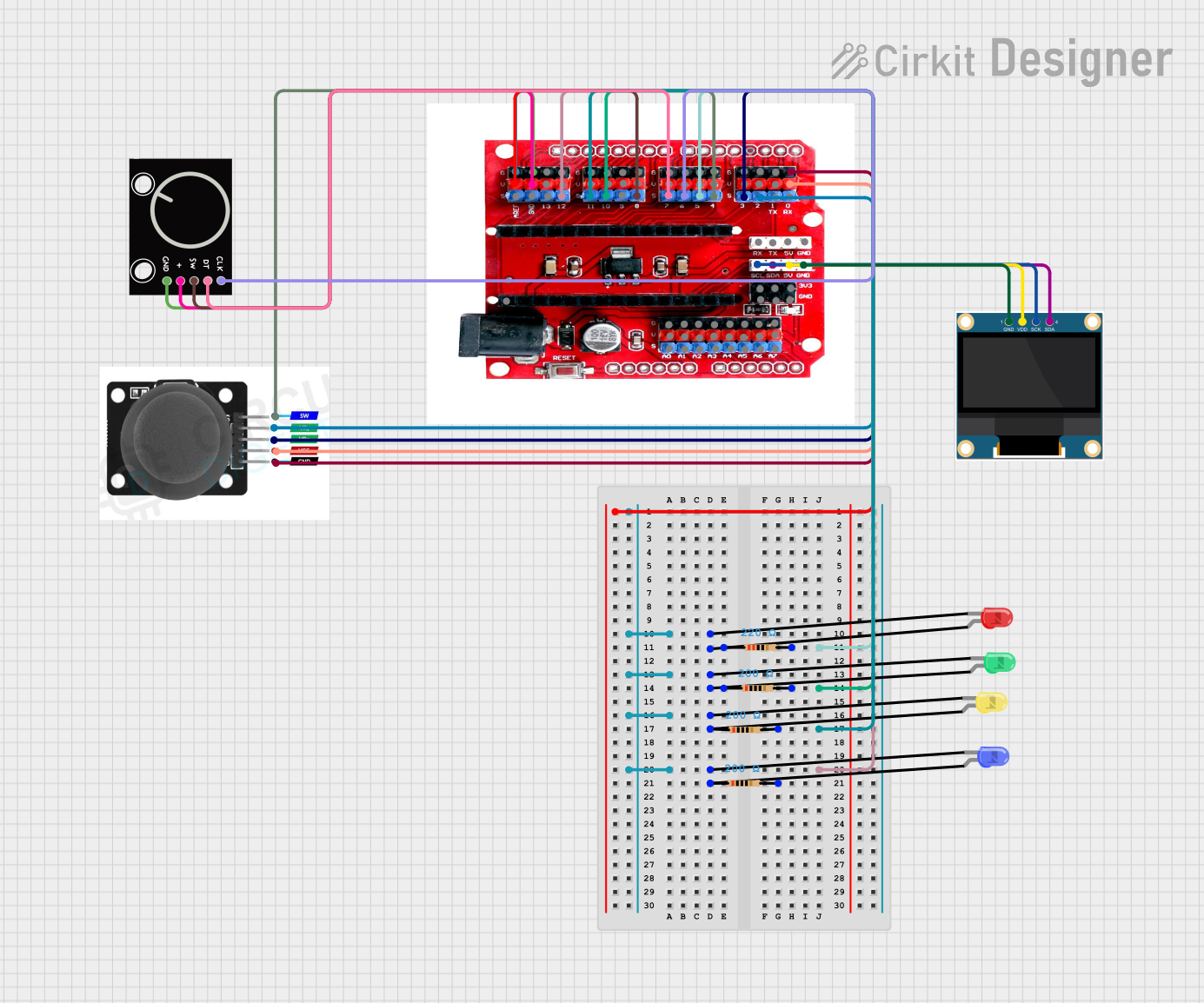 Open Project in Cirkit Designer
Explore Projects Built with IO Expansion Shield for Arduino Nano
Open Project in Cirkit DesignerOpen Project in Cirkit DesignerOpen Project in Cirkit DesignerOpen Project in Cirkit DesignerCommon Applications and Use Cases
- Robotics: Connecting multiple motors, sensors, and actuators.
- Home automation: Controlling lights, relays, and other smart devices.
- IoT projects: Interfacing with multiple sensors and communication modules.
- Educational projects: Simplifying circuit connections for beginners.
Technical Specifications
Key Technical Details
- Compatible Microcontroller: Arduino Nano
- Operating Voltage: 5V (from Arduino Nano or external power supply)
- Input Voltage (External): 6V–12V (via DC jack or terminal block)
- I/O Pins: Breakout for all Arduino Nano pins
- Additional Features:
- 3.3V and 5V power outputs
- Reset button
- Power indicator LED
- Screw terminal for external power input
- Multiple GND and VCC pins for easy connections
- Dimensions: Matches Arduino Nano footprint
Pin Configuration and Descriptions
The IO Expansion Shield breaks out all the pins of the Arduino Nano and provides additional headers for easy access. Below is the pin configuration:
| Pin | Description |
|---|---|
| Digital Pins | D0–D13: Standard digital I/O pins for sensors, actuators, and modules. |
| Analog Pins | A0–A7: Analog input pins for reading sensor data (e.g., temperature, light). |
| Power Pins | 5V, 3.3V, GND: Power outputs for external devices. |
| Reset | Reset button to restart the Arduino Nano. |
| External Power | Screw terminal and DC jack for external power input (6V–12V). |
Usage Instructions
How to Use the Component in a Circuit
- Attach the Arduino Nano: Insert the Arduino Nano into the shield's headers, ensuring proper alignment of pins.
- Connect External Power (Optional):
- If your project requires more power than the Arduino Nano can provide, connect an external power supply (6V–12V) via the DC jack or screw terminal.
- Ensure the power supply matches the voltage requirements of your connected devices.
- Connect Sensors and Actuators:
- Use the breakout headers to connect sensors, actuators, or other modules.
- Utilize the multiple GND and VCC pins for easy power distribution.
- Upload Code:
- Connect the Arduino Nano to your computer via USB, write your code in the Arduino IDE, and upload it.
Important Considerations and Best Practices
- Power Management: Avoid exceeding the current limits of the Arduino Nano or the shield. Use external power for high-current devices like motors.
- Pin Conflicts: Ensure that connected devices do not use overlapping pins unless intended.
- Voltage Compatibility: Check whether your sensors and modules operate at 3.3V or 5V and connect them accordingly.
- Secure Connections: Use the screw terminals for stable connections when working with external power supplies.
Example Code
Below is an example of how to use the IO Expansion Shield to blink an LED connected to pin D13:
// Example: Blink an LED connected to pin D13

// Define the pin for the LED
const int ledPin = 13;

void setup() {
  pinMode(ledPin, OUTPUT); // Set pin D13 as an output
}

void loop() {
  digitalWrite(ledPin, HIGH); // Turn the LED on
  delay(1000);                // Wait for 1 second
  digitalWrite(ledPin, LOW);  // Turn the LED off
  delay(1000);                // Wait for 1 second
}
Troubleshooting and FAQs
Common Issues and Solutions
Arduino Nano Not Powering On:
- Ensure the Nano is properly seated in the shield's headers.
- Check the USB connection or external power supply.
Connected Devices Not Working:
- Verify that the devices are connected to the correct pins.
- Check for loose connections or incorrect wiring.
- Ensure the devices are compatible with the shield's voltage levels.
Overheating:
- Avoid drawing excessive current through the Arduino Nano or shield.
- Use an external power supply for high-power devices.
Code Upload Fails:
- Ensure the correct board and port are selected in the Arduino IDE.
- Disconnect any devices connected to pins D0 and D1 (used for serial communication).
FAQs
Q: Can I use both 3.3V and 5V devices with this shield?
A: Yes, the shield provides both 3.3V and 5V power outputs, allowing you to connect devices with different voltage requirements.
Q: How many devices can I connect to the shield?
A: The number of devices depends on the available I/O pins and the power requirements of your devices. Ensure you do not exceed the current limits of the Arduino Nano or the shield.
Q: Can I use this shield with other Arduino boards?
A: This shield is specifically designed for the Arduino Nano. It is not compatible with other Arduino boards without modifications.
Q: Do I need an external power supply?
A: An external power supply is only needed if your project requires more power than the Arduino Nano can provide. For low-power projects, the Nano's USB power is sufficient.