How to Use thermoMETER: Examples, Pinouts, and Specs
Introduction
The thermoMETER CT-SF15 by Micro Epsilon is a high-precision infrared temperature sensor designed for non-contact temperature measurement. This device is capable of accurately measuring surface temperatures without physical contact, making it ideal for applications where traditional contact-based thermometers are impractical or impossible to use. The thermoMETER is widely used in industrial, medical, and research environments due to its reliability and precision.
Explore Projects Built with thermoMETER
Explore Projects Built with thermoMETER
Common Applications and Use Cases
- Industrial Automation: Monitoring the temperature of machinery, conveyor belts, or production lines.
- Medical Applications: Measuring body temperature or surface temperatures in sterile environments.
- HVAC Systems: Ensuring proper heating, ventilation, and air conditioning performance.
- Food Processing: Monitoring cooking or storage temperatures to ensure food safety.
- Research and Development: Measuring temperature in experimental setups or prototypes.
Technical Specifications
The following table outlines the key technical specifications of the thermoMETER CT-SF15:
| Parameter | Specification |
|---|---|
| Measurement Range | -50°C to 975°C (-58°F to 1787°F) |
| Spectral Range | 8 to 14 µm |
| Accuracy | ±1% of reading or ±1°C (whichever is greater) |
| Response Time | 150 ms |
| Emissivity Range | 0.100 to 1.100 (adjustable) |
| Power Supply | 5 to 30 V DC |
| Output Signal | 0-10 V, 4-20 mA, or digital output |
| Operating Temperature | -20°C to 85°C (-4°F to 185°F) |
| Dimensions | 28 mm diameter, 87 mm length |
| Weight | 200 g |
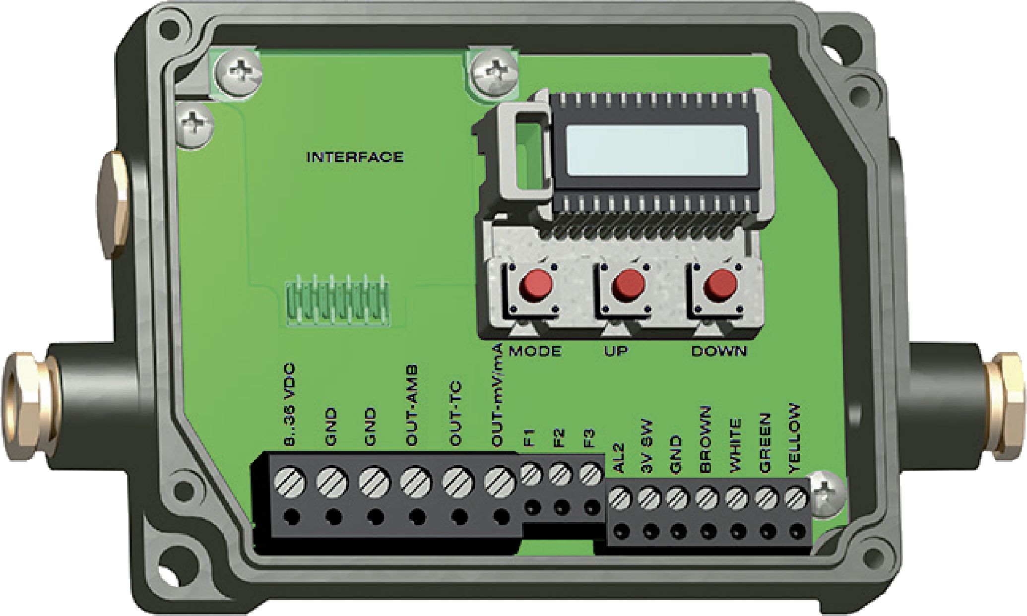
Pin Configuration and Descriptions
The thermoMETER CT-SF15 features a standard connector with the following pinout:
| Pin Number | Name | Description |
|---|---|---|
| 1 | V+ | Positive power supply (5-30 V DC) |
| 2 | GND | Ground (0 V) |
| 3 | Analog Output | Voltage or current output proportional to temperature |
| 4 | Digital Output | Digital signal for temperature data (optional) |
| 5 | Emissivity Adj | Input for adjusting emissivity |
Usage Instructions
How to Use the thermoMETER in a Circuit
- Power Supply: Connect the V+ pin to a DC power source (5-30 V) and the GND pin to ground.
- Output Signal: Choose between the analog or digital output based on your application:
- For analog output, connect the Analog Output pin to an ADC (Analog-to-Digital Converter) or a voltmeter.
- For digital output, connect the Digital Output pin to a microcontroller or data acquisition system.
- Emissivity Adjustment: If the surface emissivity differs from the default setting, adjust the emissivity input to match the target material. Refer to the material's emissivity table for accurate values.
- Mounting: Secure the thermoMETER in a stable position, ensuring it has a clear line of sight to the target surface. Avoid obstructions or reflective surfaces that may interfere with measurements.
Important Considerations and Best Practices
- Emissivity Settings: Ensure the emissivity setting matches the material being measured for accurate readings.
- Ambient Conditions: Avoid using the sensor in environments with excessive dust, smoke, or steam, as these can affect accuracy.
- Distance-to-Spot Ratio: Maintain the recommended distance-to-spot ratio to ensure the target area is fully within the sensor's field of view.
- Calibration: Periodically calibrate the sensor to maintain accuracy, especially in critical applications.
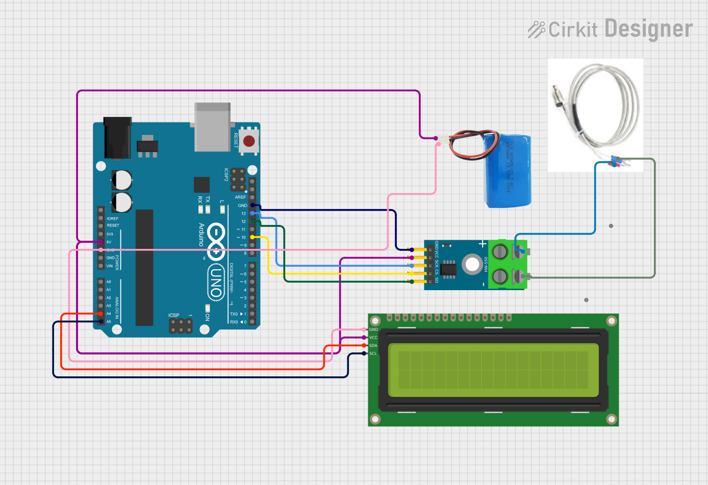
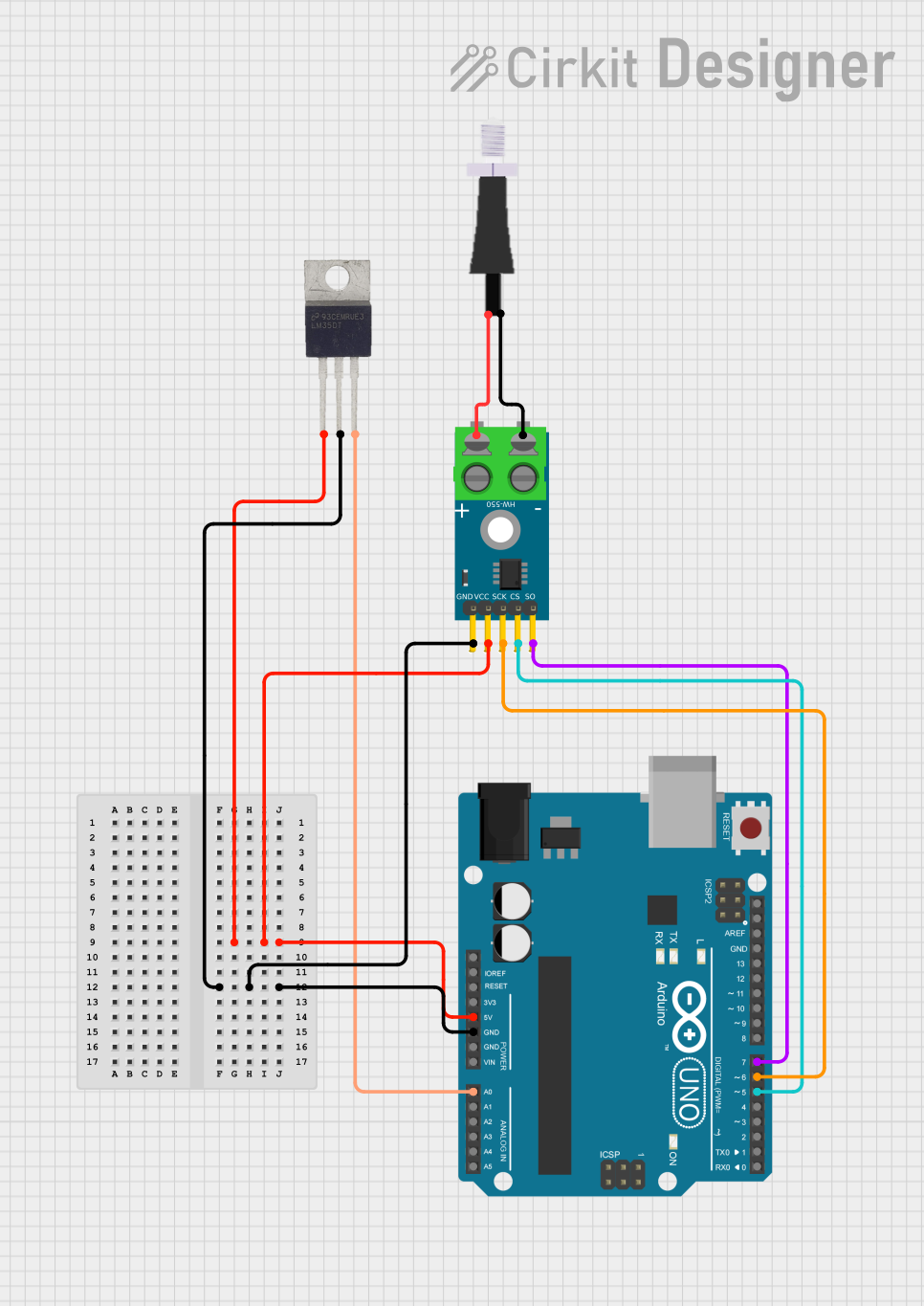
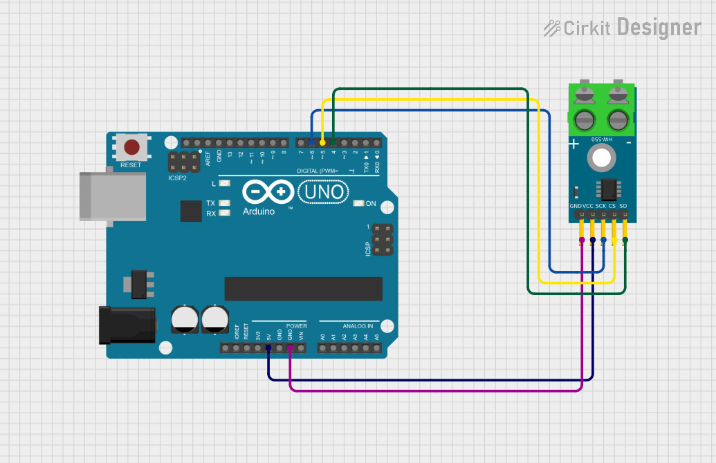
Example: Connecting to an Arduino UNO
The thermoMETER CT-SF15 can be interfaced with an Arduino UNO using its analog output. Below is an example code snippet to read temperature data:
// Define the analog pin connected to the thermoMETER's Analog Output
const int thermoMeterPin = A0;

// Variable to store the analog reading
int analogValue = 0;

// Conversion factor (adjust based on the sensor's output range and scaling)
const float voltageToTempFactor = 100.0; // Example: 10 mV per degree Celsius

void setup() {
  // Initialize serial communication for debugging
  Serial.begin(9600);
}

void loop() {
  // Read the analog value from the thermoMETER
  analogValue = analogRead(thermoMeterPin);

  // Convert the analog value to voltage (assuming 5V reference)
  float voltage = (analogValue / 1023.0) * 5.0;

  // Convert the voltage to temperature
  float temperature = voltage * voltageToTempFactor;

  // Print the temperature to the Serial Monitor
  Serial.print("Temperature: ");
  Serial.print(temperature);
  Serial.println(" °C");

  // Wait for a short period before the next reading
  delay(500);
}
Troubleshooting and FAQs
Common Issues and Solutions
No Output Signal
- Cause: Incorrect wiring or insufficient power supply.
- Solution: Verify all connections and ensure the power supply is within the specified range (5-30 V DC).
Inaccurate Temperature Readings
- Cause: Incorrect emissivity setting or environmental interference.
- Solution: Adjust the emissivity setting to match the target material and ensure the sensor's line of sight is unobstructed.
Fluctuating Readings
- Cause: Electrical noise or unstable power supply.
- Solution: Use a stable power source and shield the sensor's cables from interference.
Sensor Overheating
- Cause: Operating in an environment exceeding the sensor's temperature limits.
- Solution: Ensure the ambient temperature is within the specified operating range (-20°C to 85°C).
FAQs
Q: Can the thermoMETER measure the temperature of shiny or reflective surfaces?
A: Yes, but you must adjust the emissivity setting to account for the reflective properties of the surface. For highly reflective materials, consider using a surface treatment (e.g., matte paint or tape) to improve accuracy.
Q: How do I clean the sensor lens?
A: Use a soft, lint-free cloth and isopropyl alcohol to gently clean the lens. Avoid abrasive materials or harsh chemicals.
Q: Can the thermoMETER be used outdoors?
A: Yes, but ensure it is protected from direct exposure to rain, dust, or extreme environmental conditions. Use an appropriate housing if necessary.
Q: What is the response time of the sensor?
A: The thermoMETER CT-SF15 has a response time of 150 ms, making it suitable for dynamic applications.