How to Use DBH-12 H Bridge Motor Driver: Examples, Pinouts, and Specs
Introduction
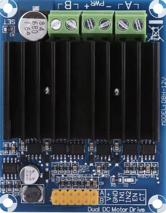
The DBH-12 H Bridge Motor Driver is an electronic device designed to control the direction and speed of DC motors. It operates by allowing current to flow through the motor in both directions, enabling forward and reverse motion. This motor driver is commonly used in robotics, automation systems, and any application requiring precise control of motor movement.
Explore Projects Built with DBH-12 H Bridge Motor Driver


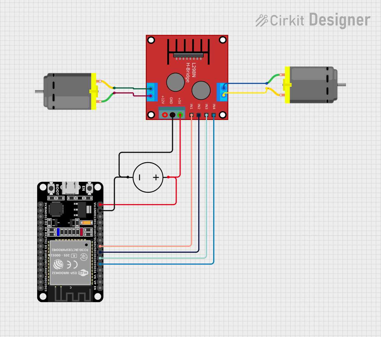
Explore Projects Built with DBH-12 H Bridge Motor Driver
Common Applications and Use Cases
- Robotics: steering and propulsion systems
- Automated machinery: conveyor belts, positioning systems
- Electric vehicles: control of propulsion motors
- Hobbyist projects: remote-controlled cars, boats, and drones
Technical Specifications
Key Technical Details
- Operating Voltage: 5V to 12V DC
- Continuous Current Rating: 2A per channel
- Peak Current: 3A per channel for short bursts
- Logic Voltage: 2.5V to 5V (compatible with most microcontrollers)
- Control Signal Input: TTL compatible
- Protection: Overcurrent and thermal shutdown features
Pin Configuration and Descriptions
| Pin Number | Pin Name | Description |
|---|---|---|
| 1 | Vcc | Motor power supply (5V-12V DC) |
| 2 | GND | Ground connection |
| 3 | A1 | Motor terminal A1 |
| 4 | A2 | Motor terminal A2 |
| 5 | B1 | Motor terminal B1 |
| 6 | B2 | Motor terminal B2 |
| 7 | Vss | Logic power supply (2.5V-5V DC) |
| 8 | IN1 | Input control signal for channel A |
| 9 | IN2 | Input control signal for channel B |
| 10 | ENA | Enable pin for channel A |
| 11 | ENB | Enable pin for channel B |
Usage Instructions
How to Use the Component in a Circuit
- Connect the motor power supply to Vcc and GND pins.
- Attach the motor terminals to A1 and A2 for motor A, and to B1 and B2 for motor B.
- Connect the logic power supply to Vss.
- Apply control signals to IN1 and IN2 to control the direction of motor A, and similarly for motor B.
- Use ENA and ENB to enable or disable the motors.
Important Considerations and Best Practices
- Ensure that the power supply voltage does not exceed the maximum rating.
- Do not exceed the continuous current rating to prevent overheating.
- Use a heat sink if operating near the peak current rating.
- Always provide a proper decoupling capacitor close to the motor driver to stabilize the power supply.
- Avoid running motors at stall current as it can quickly lead to overcurrent conditions.
Example Code for Arduino UNO
// Define motor driver pins
#define IN1 2
#define IN2 3
#define ENA 9 // PWM pin for speed control

void setup() {
  // Set motor driver pins as outputs
  pinMode(IN1, OUTPUT);
  pinMode(IN2, OUTPUT);
  pinMode(ENA, OUTPUT);
}

void loop() {
  // Set motor A direction to forward
  digitalWrite(IN1, HIGH);
  digitalWrite(IN2, LOW);
  // Set speed to 50%
  analogWrite(ENA, 127);
  delay(2000); // Run for 2 seconds

  // Set motor A direction to reverse
  digitalWrite(IN1, LOW);
  digitalWrite(IN2, HIGH);
  // Set speed to 50%
  analogWrite(ENA, 127);
  delay(2000); // Run for 2 seconds

  // Stop motor A
  digitalWrite(IN1, LOW);
  digitalWrite(IN2, LOW);
  delay(1000); // Stop for 1 second
}
Troubleshooting and FAQs
Common Issues
- Motor not running: Check power supply connections and ensure that the logic signals are being applied correctly.
- Overheating: Ensure the current does not exceed the continuous rating and that a heat sink is used if necessary.
- Erratic behavior: Verify that the decoupling capacitors are in place and that there is no interference with the control signals.
Solutions and Tips for Troubleshooting
- Double-check wiring and solder joints for any loose connections.
- Measure the voltage at the motor driver's power pins to ensure it is within the specified range.
- Use a multimeter to verify the logic level of control signals.
- If the motor driver shuts down due to overcurrent, allow it to cool down before restarting.
FAQs
Q: Can I control two motors independently with the DBH-12? A: Yes, the DBH-12 has two channels, allowing for independent control of two motors.
Q: What should I do if the motor driver gets hot during operation? A: Reduce the load on the motor, check for any shorts, and ensure proper heat sinking.
Q: Is it possible to control the speed of the motor using the DBH-12? A: Yes, by applying PWM signals to the ENA and ENB pins, you can control the speed of the motors.
Q: Can I use the DBH-12 with a microcontroller operating at 3.3V logic? A: The DBH-12 is compatible with logic voltages from 2.5V to 5V, so it can be used with 3.3V logic microcontrollers.