How to Use SDA & SCL Bridge: Examples, Pinouts, and Specs
Introduction
The SDA & SCL Bridge is a circuit component designed to facilitate communication between devices using the I2C (Inter-Integrated Circuit) protocol. It connects the Serial Data Line (SDA) and Serial Clock Line (SCL) between devices, ensuring proper signal integrity and timing. This component is essential in systems where multiple I2C devices are connected, as it helps maintain reliable communication by addressing issues such as signal degradation and timing mismatches.
Explore Projects Built with SDA & SCL Bridge


Explore Projects Built with SDA & SCL Bridge
Common Applications and Use Cases
- I2C communication in microcontroller-based systems (e.g., Arduino, Raspberry Pi)
- Bridging I2C devices with different voltage levels
- Extending the range of I2C communication in complex circuits
- Ensuring signal integrity in high-speed I2C applications
Technical Specifications
The SDA & SCL Bridge is designed to work seamlessly in I2C communication systems. Below are its key technical details:
Key Technical Details
- Operating Voltage: 1.8V to 5.5V
- Maximum I2C Clock Frequency: 400 kHz (Standard Mode) or 1 MHz (Fast Mode)
- Input Impedance: High impedance to prevent signal loading
- Output Drive Strength: Capable of driving up to 20 mA
- Voltage Level Translation: Supports bidirectional level shifting between 1.8V and 5V
- Operating Temperature Range: -40°C to +85°C
Pin Configuration and Descriptions
The SDA & SCL Bridge typically has the following pin configuration:
| Pin Name | Description |
|---|---|
| VCC | Power supply input (1.8V to 5.5V) |
| GND | Ground connection |
| SDA_IN | Serial Data Line input from the master or upstream device |
| SCL_IN | Serial Clock Line input from the master or upstream device |
| SDA_OUT | Serial Data Line output to the slave or downstream device |
| SCL_OUT | Serial Clock Line output to the slave or downstream device |
| EN | Enable pin to activate or deactivate the bridge (active high) |
Usage Instructions
The SDA & SCL Bridge is straightforward to use in I2C communication systems. Follow the steps below to integrate it into your circuit:
How to Use the Component in a Circuit
- Power the Bridge: Connect the VCC pin to the appropriate power supply (1.8V to 5.5V) and the GND pin to the ground.
- Connect the I2C Lines:
- Connect the SDA_IN and SCL_IN pins to the master device or upstream I2C bus.
- Connect the SDA_OUT and SCL_OUT pins to the slave device or downstream I2C bus.
- Enable the Bridge: If the bridge has an enable pin (EN), ensure it is pulled high to activate the component.
- Add Pull-Up Resistors: Place pull-up resistors (typically 4.7kΩ) on the SDA and SCL lines to ensure proper I2C operation.
- Verify Voltage Levels: If the bridge is used for level shifting, ensure the voltage levels on both sides are within the supported range.
Important Considerations and Best Practices
- Pull-Up Resistors: Ensure that appropriate pull-up resistors are used on both the SDA and SCL lines. The resistor value depends on the bus capacitance and desired speed.
- Signal Integrity: Keep the SDA and SCL lines as short as possible to minimize noise and signal degradation.
- Voltage Compatibility: Verify that the voltage levels of the connected devices are compatible with the bridge's specifications.
- Enable Pin: If the bridge includes an enable pin, ensure it is properly controlled to avoid unintentional disconnection.
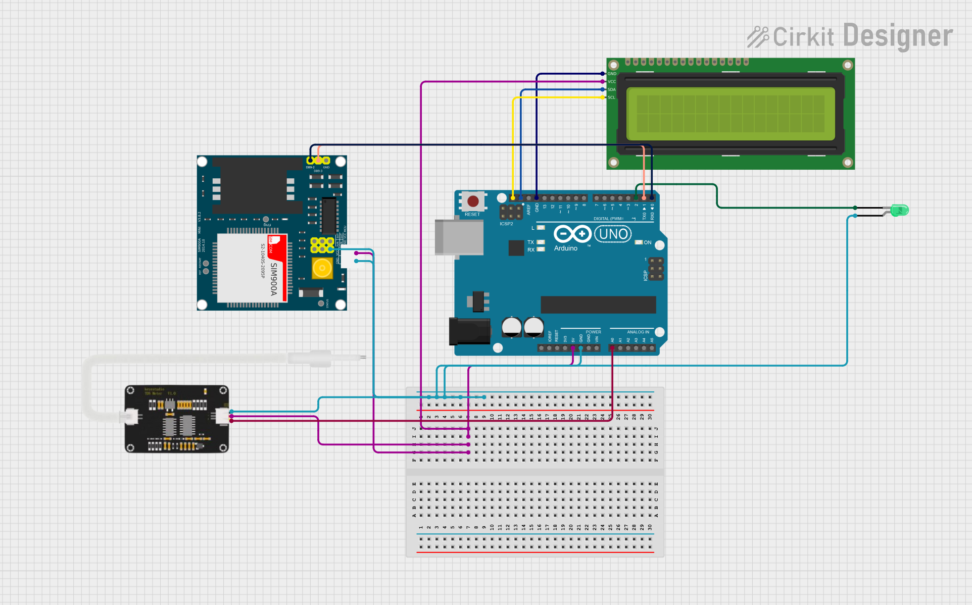
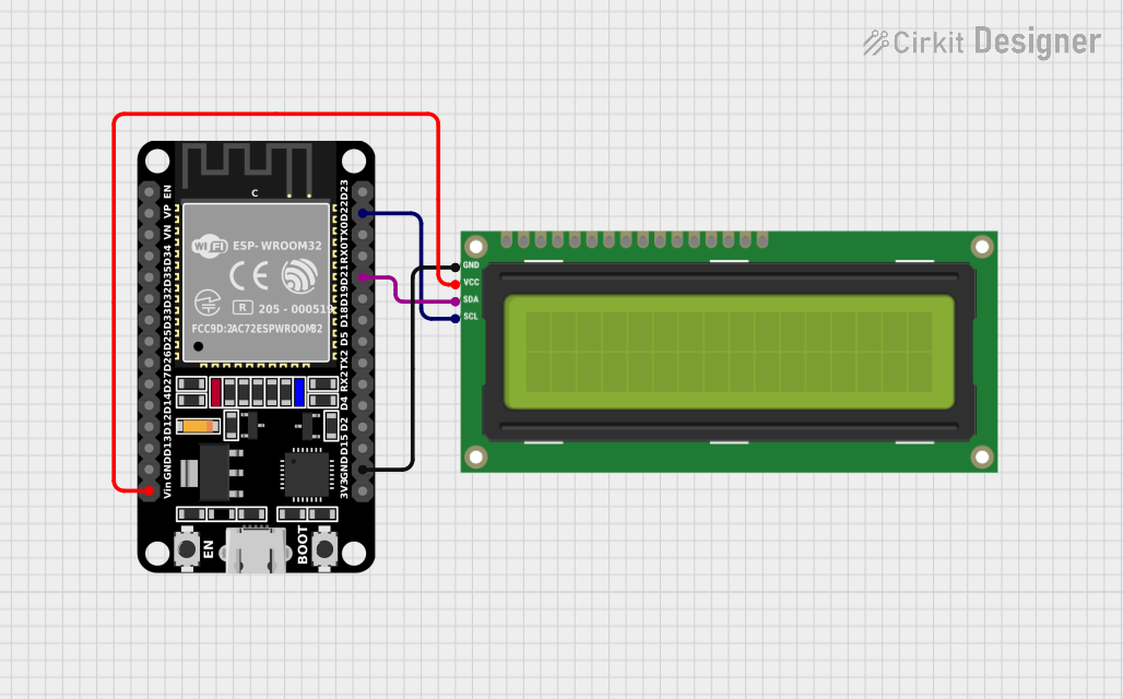
Example: Using the SDA & SCL Bridge with an Arduino UNO
Below is an example of how to use the SDA & SCL Bridge in an Arduino-based I2C system:
Circuit Diagram
- Connect the SDA_IN and SCL_IN pins of the bridge to the Arduino's SDA (A4) and SCL (A5) pins, respectively.
- Connect the SDA_OUT and SCL_OUT pins to the I2C slave device.
- Add pull-up resistors (4.7kΩ) to the SDA and SCL lines.
Arduino Code
#include <Wire.h> // Include the Wire library for I2C communication

void setup() {
  Wire.begin(); // Initialize the I2C bus as a master
  Serial.begin(9600); // Start serial communication for debugging

  // Send a test message to an I2C slave device with address 0x3C
  Wire.beginTransmission(0x3C); // Begin communication with slave
  Wire.write("Hello, I2C!"); // Send data to the slave
  Wire.endTransmission(); // End the transmission

  Serial.println("Message sent to I2C slave.");
}

void loop() {
  // No repeated actions in this example
}
Troubleshooting and FAQs
Common Issues and Solutions
No Communication Between Devices
- Cause: Missing or incorrect pull-up resistors.
- Solution: Ensure pull-up resistors (e.g., 4.7kΩ) are connected to the SDA and SCL lines.
Voltage Level Mismatch
- Cause: Devices on the I2C bus operate at different voltage levels.
- Solution: Use the SDA & SCL Bridge for proper level shifting between devices.
Signal Noise or Degradation
- Cause: Long SDA and SCL lines or high capacitance on the bus.
- Solution: Shorten the I2C lines and reduce the number of connected devices if possible.
Bridge Not Functioning
- Cause: The enable pin (EN) is not activated.
- Solution: Ensure the EN pin is pulled high to activate the bridge.
FAQs
Q: Can the SDA & SCL Bridge be used for SPI communication?
A: No, the SDA & SCL Bridge is specifically designed for I2C communication and is not compatible with SPI.
Q: What is the maximum number of devices that can be connected using the bridge?
A: The maximum number of devices depends on the total bus capacitance and the strength of the pull-up resistors. Typically, up to 128 devices can be addressed on an I2C bus.
Q: Can the bridge handle high-speed I2C communication?
A: Yes, the bridge supports I2C clock frequencies up to 1 MHz (Fast Mode).
Q: Is the bridge necessary for all I2C systems?
A: No, the bridge is only required in systems with voltage level mismatches, long communication lines, or signal integrity issues.