Cirkit Designer
Your all-in-one circuit design IDE
Home /
Component Documentation
How to Use L293D Motor Driver Expansion Board Mini 4CH 4 Channel Motor Drive: Examples, Pinouts, and Specs
Introduction
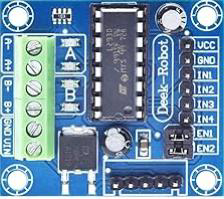
The L293D Motor Driver Expansion Board Mini 4CH 4 Channel Motor Drive by DKARDU is a compact and versatile motor driver board designed to control up to four DC motors or two stepper motors. Utilizing the L293D IC, this board is ideal for robotics and automation projects, providing an efficient and straightforward solution for motor control.
Explore Projects Built with L293D Motor Driver Expansion Board Mini 4CH 4 Channel Motor Drive
Arduino-Powered Battery-Operated Dual DC Motor Control System
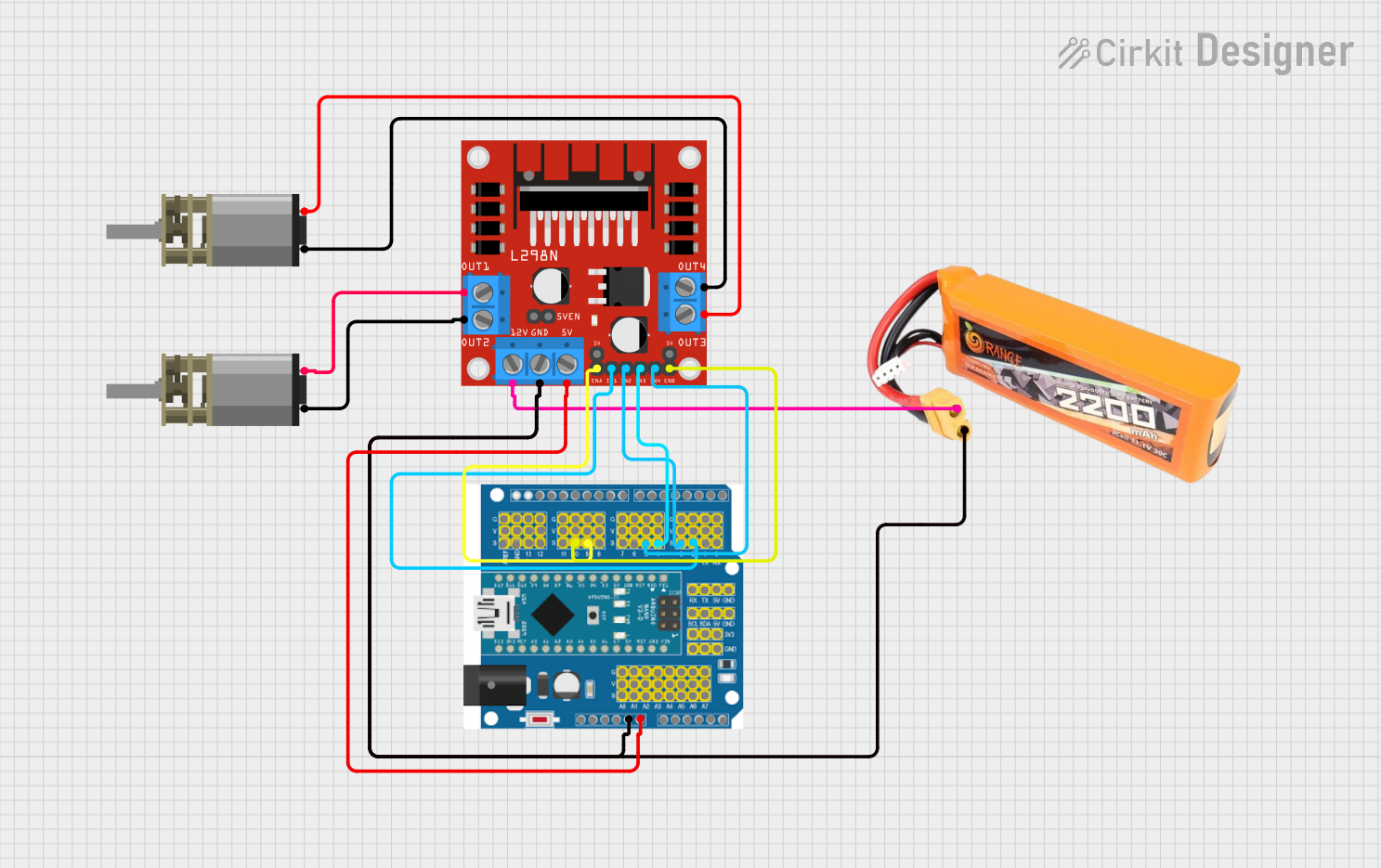
This circuit uses an Arduino Expansion Board to control two DC Mini Metal Gear Motors via an L298N DC motor driver. The motors are powered by a 2200mAh LiPo battery, and the Arduino sends control signals to the motor driver to manage the direction and speed of the motors.
Raspberry Pi 4B Controlled Robotic Car with Ultrasonic Sensor and Motor Drivers
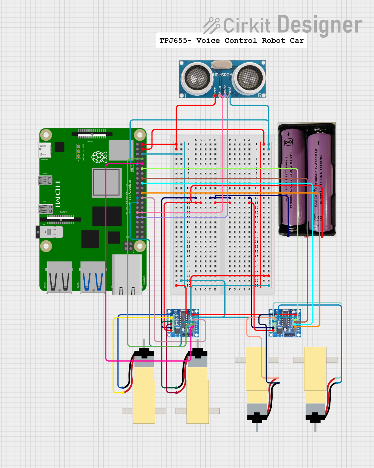
This circuit is a motor control system using a Raspberry Pi 4B to drive four hobby gearmotors through two L293D motor driver expansion boards. The Raspberry Pi also interfaces with an ultrasonic sensor for distance measurement, enabling autonomous or remote-controlled operation of the motors based on sensor input.
Arduino-Based Line Following Robot with L298N Motor Driver and IR Sensor Array
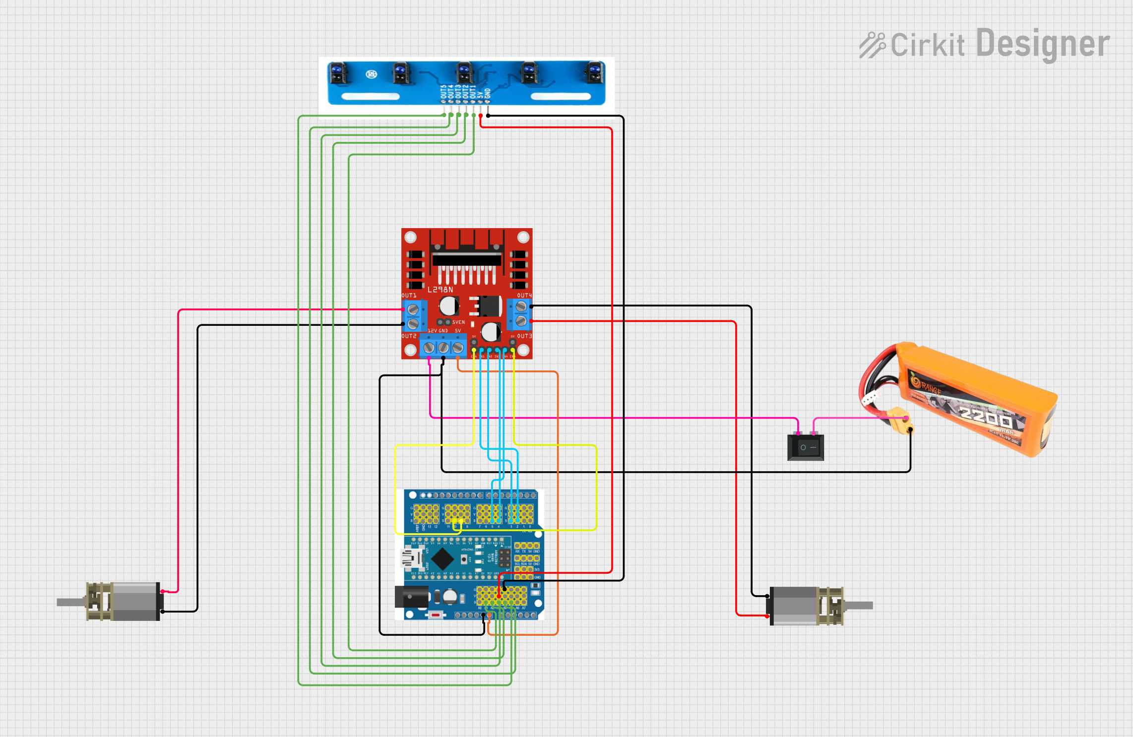
This circuit is a line-following robot that uses an Arduino Expansion Board to control two DC motors via an L298N motor driver. The robot uses a 5-channel IR sensor array to detect the line and adjust the motor speeds accordingly, powered by a 2200mAH LiPo battery and controlled through a PID algorithm implemented in the Arduino code.
Arduino UNO Wi-Fi Controlled DC Motor Driver with Battery Management System

This circuit is a motor control system powered by a 3s 20A BMS and 18650 Li-ion batteries, which drives two DC Mini Metal Gear Motors using an L298N motor driver. The Arduino UNO R4 WiFi microcontroller is used to control the motor driver, and a buck converter provides regulated power to a Type-C port.
Explore Projects Built with L293D Motor Driver Expansion Board Mini 4CH 4 Channel Motor Drive
Arduino-Powered Battery-Operated Dual DC Motor Control System
This circuit uses an Arduino Expansion Board to control two DC Mini Metal Gear Motors via an L298N DC motor driver. The motors are powered by a 2200mAh LiPo battery, and the Arduino sends control signals to the motor driver to manage the direction and speed of the motors.
Raspberry Pi 4B Controlled Robotic Car with Ultrasonic Sensor and Motor Drivers
This circuit is a motor control system using a Raspberry Pi 4B to drive four hobby gearmotors through two L293D motor driver expansion boards. The Raspberry Pi also interfaces with an ultrasonic sensor for distance measurement, enabling autonomous or remote-controlled operation of the motors based on sensor input.
Arduino-Based Line Following Robot with L298N Motor Driver and IR Sensor Array
This circuit is a line-following robot that uses an Arduino Expansion Board to control two DC motors via an L298N motor driver. The robot uses a 5-channel IR sensor array to detect the line and adjust the motor speeds accordingly, powered by a 2200mAH LiPo battery and controlled through a PID algorithm implemented in the Arduino code.
Arduino UNO Wi-Fi Controlled DC Motor Driver with Battery Management System
This circuit is a motor control system powered by a 3s 20A BMS and 18650 Li-ion batteries, which drives two DC Mini Metal Gear Motors using an L298N motor driver. The Arduino UNO R4 WiFi microcontroller is used to control the motor driver, and a buck converter provides regulated power to a Type-C port.
Common Applications and Use Cases
- Robotics: Control multiple motors for robot movement and actuation.
- Automation Projects: Drive motors in automated systems such as conveyor belts, automated doors, and more.
- DIY Projects: Perfect for hobbyists building motorized models, vehicles, and other creative projects.
- Educational Purposes: Great for teaching motor control concepts in electronics and robotics courses.
Technical Specifications
Key Technical Details
| Specification | Value |
|---|---|
| Operating Voltage | 4.5V to 36V |
| Output Current | 600mA per channel (peak 1.2A) |
| Number of Channels | 4 (for DC motors) |
| Motor Type | DC motors, Stepper motors |
| Control Logic | TTL compatible |
| Dimensions | 50mm x 50mm x 15mm |
Pin Configuration and Descriptions
Power and Control Pins
| Pin Name | Description |
|---|---|
| VCC | Power supply for the motor (4.5V-36V) |
| GND | Ground |
| 5V | Logic voltage supply (5V) |
| EN1 | Enable pin for Motor 1 and Motor 2 |
| EN2 | Enable pin for Motor 3 and Motor 4 |
Motor Control Pins
| Pin Name | Description |
|---|---|
| IN1 | Input 1 for Motor 1 |
| IN2 | Input 2 for Motor 1 |
| IN3 | Input 1 for Motor 2 |
| IN4 | Input 2 for Motor 2 |
| IN5 | Input 1 for Motor 3 |
| IN6 | Input 2 for Motor 3 |
| IN7 | Input 1 for Motor 4 |
| IN8 | Input 2 for Motor 4 |
| OUT1 | Output 1 for Motor 1 |
| OUT2 | Output 2 for Motor 1 |
| OUT3 | Output 1 for Motor 2 |
| OUT4 | Output 2 for Motor 2 |
| OUT5 | Output 1 for Motor 3 |
| OUT6 | Output 2 for Motor 3 |
| OUT7 | Output 1 for Motor 4 |
| OUT8 | Output 2 for Motor 4 |
Usage Instructions
How to Use the Component in a Circuit
Power Connections:
- Connect the VCC pin to the motor power supply (4.5V to 36V).
- Connect the GND pin to the ground of the power supply.
- Connect the 5V pin to the 5V output of your microcontroller (e.g., Arduino UNO).
Motor Connections:
- Connect the motor terminals to the corresponding OUT pins (OUT1-OUT8).
Control Connections:
- Connect the control pins (IN1-IN8) to the digital output pins of your microcontroller.
- Use the EN1 and EN2 pins to enable or disable the motors.
Important Considerations and Best Practices
- Heat Dissipation: Ensure proper heat dissipation as the L293D IC can get hot during operation.
- Current Limiting: Do not exceed the maximum current rating of 600mA per channel to avoid damage.
- Power Supply: Use a stable power supply to prevent voltage fluctuations that could affect motor performance.
Example Code for Arduino UNO
// Example code to control two DC motors using L293D Motor Driver Board
// Connect IN1, IN2, IN3, IN4 to Arduino pins 2, 3, 4, 5 respectively

#define IN1 2
#define IN2 3
#define IN3 4
#define IN4 5

void setup() {
  // Set all control pins as output
  pinMode(IN1, OUTPUT);
  pinMode(IN2, OUTPUT);
  pinMode(IN3, OUTPUT);
  pinMode(IN4, OUTPUT);
}

void loop() {
  // Move Motor 1 forward
  digitalWrite(IN1, HIGH);
  digitalWrite(IN2, LOW);

  // Move Motor 2 backward
  digitalWrite(IN3, LOW);
  digitalWrite(IN4, HIGH);

  delay(2000); // Run motors for 2 seconds

  // Stop both motors
  digitalWrite(IN1, LOW);
  digitalWrite(IN2, LOW);
  digitalWrite(IN3, LOW);
  digitalWrite(IN4, LOW);

  delay(2000); // Wait for 2 seconds
}
Troubleshooting and FAQs
Common Issues Users Might Face
Motors Not Running:
- Solution: Check power connections and ensure the power supply is within the specified range. Verify that the enable pins (EN1, EN2) are set correctly.
Overheating:
- Solution: Ensure proper ventilation and consider adding a heat sink to the L293D IC. Check if the current draw of the motors is within the specified limits.
Erratic Motor Behavior:
- Solution: Ensure stable power supply and proper grounding. Check for loose connections and ensure control signals are correctly applied.
Solutions and Tips for Troubleshooting
- Double-Check Connections: Ensure all connections are secure and correctly placed according to the pin configuration.
- Use a Multimeter: Measure voltage levels at various points to ensure proper power delivery.
- Consult Datasheets: Refer to the L293D IC datasheet for detailed electrical characteristics and limitations.
By following this documentation, users can effectively utilize the L293D Motor Driver Expansion Board Mini 4CH 4 Channel Motor Drive in their projects, ensuring reliable and efficient motor control.