How to Use LAMP - RUN INDICATOR: Examples, Pinouts, and Specs
Introduction
The LAMP - RUN INDICATOR (Manufacturer: Schneider, Part ID: XB4-BVM3) is a high-quality indicator lamp designed to visually signal the operational status of a device or system. It typically illuminates when the associated equipment is powered on or functioning correctly. This component is widely used in industrial control panels, machinery, and automation systems to provide clear and immediate status feedback.
Explore Projects Built with LAMP - RUN INDICATOR

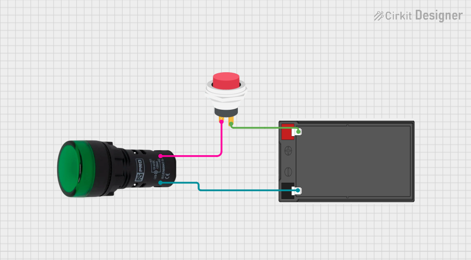
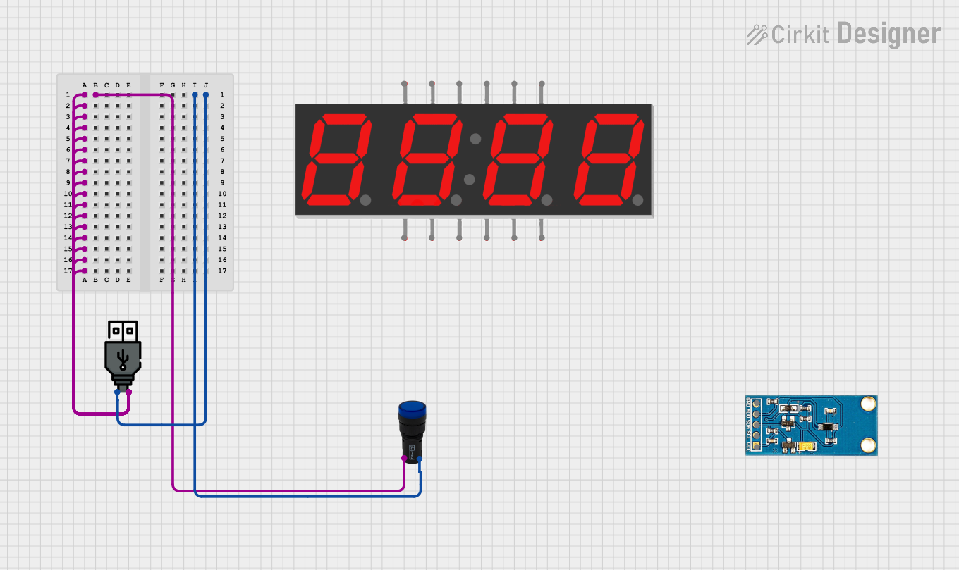
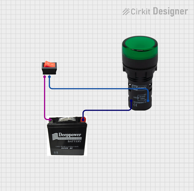
Explore Projects Built with LAMP - RUN INDICATOR
Common Applications and Use Cases
- Industrial control panels for status indication
- Machinery and equipment operational feedback
- Power-on indicators for electrical systems
- Automation systems requiring visual status signals
- Safety and fault indication in industrial environments
Technical Specifications
Key Technical Details
| Parameter | Value |
|---|---|
| Manufacturer | Schneider |
| Part ID | XB4-BVM3 |
| Operating Voltage | 24V AC/DC |
| Power Consumption | 1.2W |
| Illumination Color | Green |
| Mounting Type | Panel Mount |
| Bezel Material | Metal (Chrome Finish) |
| Lamp Type | LED |
| Operating Temperature | -25°C to +70°C |
| IP Rating | IP66 (Dust-tight and water-resistant) |
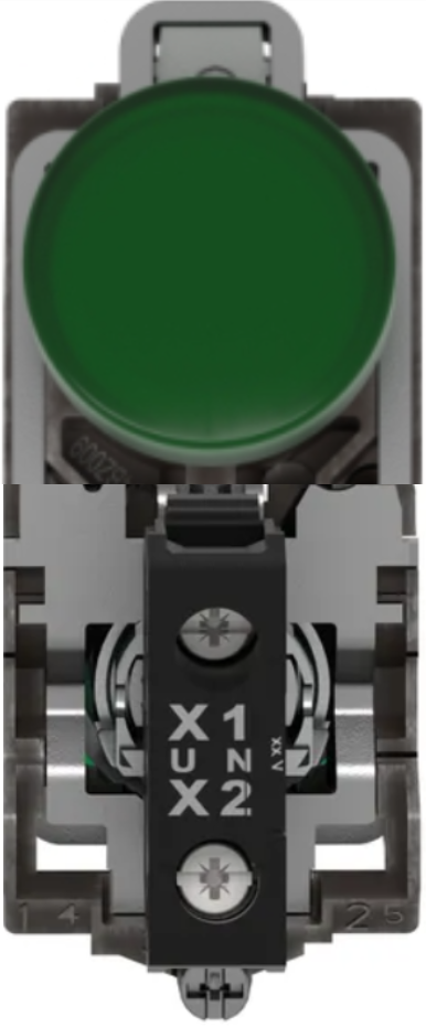
Pin Configuration and Descriptions
The XB4-BVM3 lamp has a simple terminal configuration for easy integration into circuits. Below is the pin description:
| Terminal Number | Description |
|---|---|
| 1 | Positive terminal (24V AC/DC input) |
| 2 | Negative terminal (Ground) |
Usage Instructions
How to Use the Component in a Circuit
Mounting the Lamp:
- Drill a 22mm hole in the panel where the lamp will be installed.
- Insert the lamp into the hole and secure it using the provided mounting hardware.
Wiring the Lamp:
- Connect the positive terminal (Terminal 1) to the 24V AC/DC power supply.
- Connect the negative terminal (Terminal 2) to the ground.
- Ensure all connections are secure and insulated to prevent short circuits.
Testing the Lamp:
- Power on the system to verify that the lamp illuminates when the device is operational.
- If the lamp does not light up, check the wiring and power supply.
Important Considerations and Best Practices
- Ensure the operating voltage matches the lamp's rated voltage (24V AC/DC).
- Avoid exposing the lamp to temperatures outside the specified range (-25°C to +70°C).
- Use appropriate wire gauges for the connections to handle the current safely.
- Regularly inspect the lamp for signs of wear or damage, especially in harsh environments.
- For outdoor or wet environments, ensure the panel maintains the IP66 rating to protect the lamp.
Example: Connecting to an Arduino UNO
The XB4-BVM3 can be used with an Arduino UNO to indicate the status of a system. Below is an example circuit and code:
Circuit Setup
- Connect Terminal 1 of the lamp to a 24V DC power supply through a relay module controlled by the Arduino.
- Connect Terminal 2 of the lamp to the ground of the power supply.
- Use a relay module to safely interface the Arduino with the 24V lamp.
Arduino Code
// Example code to control the XB4-BVM3 lamp using an Arduino UNO
// The lamp is connected to a relay module, which is controlled by pin 7.

const int relayPin = 7; // Pin connected to the relay module

void setup() {
  pinMode(relayPin, OUTPUT); // Set relay pin as output
  digitalWrite(relayPin, LOW); // Ensure the relay is off initially
}

void loop() {
  // Turn the lamp on
  digitalWrite(relayPin, HIGH);
  delay(1000); // Keep the lamp on for 1 second

  // Turn the lamp off
  digitalWrite(relayPin, LOW);
  delay(1000); // Keep the lamp off for 1 second
}
Troubleshooting and FAQs
Common Issues and Solutions
| Issue | Possible Cause | Solution |
|---|---|---|
| Lamp does not illuminate | Incorrect wiring or loose connections | Verify wiring and ensure secure connections. |
| Lamp flickers | Unstable power supply | Check the power supply for stability. |
| Lamp overheats | Voltage exceeds 24V AC/DC | Ensure the input voltage is within the specified range. |
| Lamp fails to turn off | Faulty relay or control circuit | Inspect the relay and control circuit for issues. |
FAQs
Q1: Can the XB4-BVM3 be used with a 12V power supply?
A1: No, the lamp is designed for 24V AC/DC operation. Using a 12V supply may result in insufficient illumination or failure to operate.
Q2: Is the lamp suitable for outdoor use?
A2: Yes, the lamp has an IP66 rating, making it dust-tight and water-resistant. However, ensure the panel maintains the same IP rating.
Q3: Can the lamp be replaced if it fails?
A3: The XB4-BVM3 uses an LED, which has a long lifespan. If it fails, the entire unit may need to be replaced as it is not designed for user-serviceable parts.
Q4: What is the maximum current the lamp draws?
A4: The lamp consumes 1.2W at 24V, which corresponds to a current of approximately 0.05A.
By following this documentation, users can effectively integrate and troubleshoot the Schneider XB4-BVM3 LAMP - RUN INDICATOR in their systems.