
How to Use Adafruit 2.0 inch 240x320 IPS TFT: Examples, Pinouts, and Specs
 Design with Adafruit 2.0 inch 240x320 IPS TFT in Cirkit Designer
Introduction
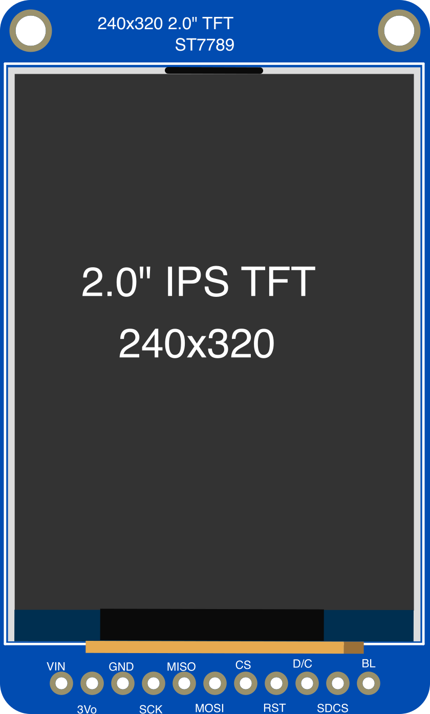
The Adafruit 2.0 inch 240x320 IPS TFT (Manufacturer Part ID: 4311) is a compact display module designed for embedded systems and portable devices. It features a 2.0-inch diagonal screen with a resolution of 240x320 pixels, utilizing In-Plane Switching (IPS) technology to deliver wide viewing angles and vibrant color reproduction. This display is ideal for applications requiring high-quality visuals in a small form factor, such as handheld devices, IoT interfaces, and custom user interfaces.
Explore Projects Built with Adafruit 2.0 inch 240x320 IPS TFT
 Open Project in Cirkit Designer
 Open Project in Cirkit Designer
 Open Project in Cirkit Designer
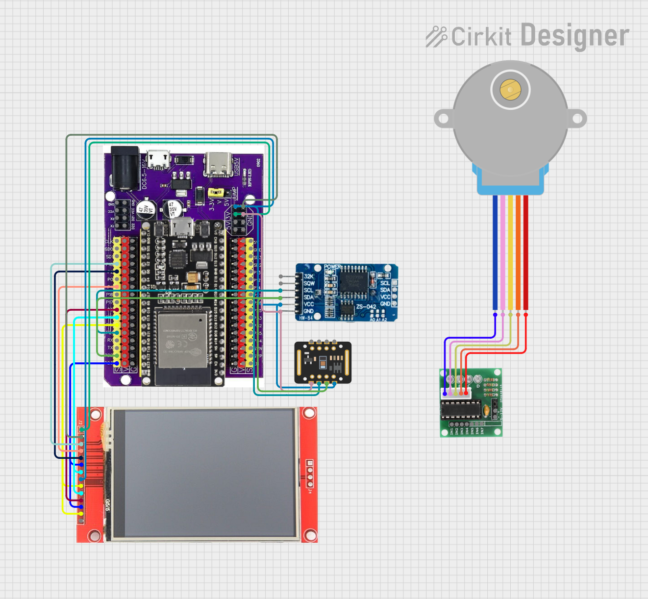 Open Project in Cirkit Designer
Explore Projects Built with Adafruit 2.0 inch 240x320 IPS TFT
Open Project in Cirkit DesignerOpen Project in Cirkit DesignerOpen Project in Cirkit DesignerOpen Project in Cirkit DesignerCommon Applications
- Portable devices and handheld electronics
- IoT dashboards and control panels
- Wearable technology
- Embedded systems requiring graphical displays
- Prototyping and hobbyist projects
Technical Specifications
Key Technical Details
| Parameter | Specification |
|---|---|
| Screen Size | 2.0 inches (diagonal) |
| Resolution | 240x320 pixels |
| Display Technology | IPS (In-Plane Switching) |
| Interface | SPI (Serial Peripheral Interface) |
| Operating Voltage | 3.3V logic (5V-tolerant inputs) |
| Backlight | LED, adjustable brightness |
| Viewing Angle | Wide (IPS technology) |
| Dimensions | 35.5mm x 52.5mm x 5.0mm |
| Weight | ~10g |
Pin Configuration and Descriptions
The Adafruit 2.0 inch 240x320 IPS TFT module has the following pinout:
| Pin Name | Pin Number | Description |
|---|---|---|
| VIN | 1 | Power input (3.3V to 5V). Powers the display and backlight. |
| GND | 2 | Ground connection. |
| SCK | 3 | SPI clock input. |
| MOSI | 4 | SPI data input (Master Out, Slave In). |
| CS | 5 | Chip Select. Active low to enable communication with the display. |
| DC | 6 | Data/Command select. High for data, low for command. |
| RST | 7 | Reset pin. Active low to reset the display. |
| BL | 8 | Backlight control. Can be connected to PWM for brightness adjustment. |
Usage Instructions
How to Use the Component in a Circuit
- Power Supply: Connect the
VINpin to a 3.3V or 5V power source and theGNDpin to ground. - SPI Communication: Connect the
SCKandMOSIpins to the corresponding SPI pins on your microcontroller. - Control Pins:
- Connect the
CSpin to a GPIO pin on your microcontroller to enable/disable communication. - Connect the
DCpin to a GPIO pin to toggle between data and command modes. - Connect the
RSTpin to a GPIO pin or tie it to the reset line of your microcontroller.
- Connect the
- Backlight Control: Connect the
BLpin to a PWM-capable GPIO pin for adjustable brightness or tie it toVINfor full brightness.
Important Considerations and Best Practices
- Voltage Levels: Ensure that the logic levels of your microcontroller are compatible with the display (3.3V logic; 5V-tolerant inputs).
- SPI Speed: Use an appropriate SPI clock speed (typically up to 10 MHz) to ensure reliable communication.
- Backlight Power: Avoid driving the backlight directly from a GPIO pin; use a transistor or PWM driver if needed.
- Reset Pin: If not using the
RSTpin, connect it toVINthrough a pull-up resistor.
Example Code for Arduino UNO
Below is an example of how to use the Adafruit 2.0 inch 240x320 IPS TFT with an Arduino UNO. This example uses the Adafruit GFX and Adafruit ST7789 libraries.
#include <Adafruit_GFX.h>    // Core graphics library
#include <Adafruit_ST7789.h> // Driver for the ST7789 display
#include <SPI.h>             // SPI library

// Define pin connections
#define TFT_CS   10  // Chip Select pin
#define TFT_DC    9  // Data/Command pin
#define TFT_RST   8  // Reset pin

// Initialize the display object
Adafruit_ST7789 tft = Adafruit_ST7789(TFT_CS, TFT_DC, TFT_RST);

void setup() {
  // Initialize serial communication for debugging
  Serial.begin(9600);
  Serial.println("Adafruit 2.0 inch 240x320 IPS TFT Test");

  // Initialize the display
  tft.init(240, 320); // Initialize with width=240 and height=320
  tft.setRotation(1); // Set display orientation (0-3)

  // Fill the screen with a solid color
  tft.fillScreen(ST77XX_BLACK);

  // Display a message
  tft.setTextColor(ST77XX_WHITE);
  tft.setTextSize(2);
  tft.setCursor(10, 10);
  tft.println("Hello, World!");
}

void loop() {
  // Add your code here to update the display
}
Notes:
- Install the Adafruit GFX and Adafruit ST7789 libraries via the Arduino Library Manager before running the code.
- Adjust the
TFT_CS,TFT_DC, andTFT_RSTpin definitions to match your wiring.
Troubleshooting and FAQs
Common Issues and Solutions
Display Not Turning On:
- Verify the power connections (
VINandGND). - Ensure the
RSTpin is properly connected or tied high.
- Verify the power connections (
No Image or Incorrect Display:
- Check the SPI connections (
SCK,MOSI,CS,DC). - Ensure the correct initialization parameters (e.g., resolution) are used in the code.
- Check the SPI connections (
Flickering or Dim Backlight:
- Verify the backlight (
BL) pin connection. - Use a stable power source for the backlight.
- Verify the backlight (
Incorrect Colors or Artifacts:
- Ensure the SPI clock speed is within the recommended range.
- Check for loose or poor-quality connections.
FAQs
Q: Can I use this display with a 5V microcontroller?
A: Yes, the display's inputs are 5V-tolerant, but the logic level is 3.3V. Ensure proper connections.
Q: How do I adjust the brightness?
A: Connect the BL pin to a PWM-capable GPIO pin and use PWM to control brightness.
Q: What is the maximum SPI clock speed?
A: The display typically supports SPI clock speeds up to 10 MHz for reliable operation.
Q: Can I use this display in portrait and landscape modes?
A: Yes, the display orientation can be changed using the setRotation() function in the Adafruit ST7789 library.