How to Use ESP32: Examples, Pinouts, and Specs
Introduction
The ESP32, developed by Espressif Systems, is a low-cost, low-power system on a chip (SoC) that integrates Wi-Fi and Bluetooth capabilities. It is widely used in Internet of Things (IoT) applications, embedded systems, and smart devices due to its versatility, high performance, and energy efficiency. The ESP32 is equipped with a dual-core processor, a rich set of peripherals, and extensive GPIO options, making it suitable for a wide range of projects, from home automation to industrial control systems.
Explore Projects Built with ESP32


Explore Projects Built with ESP32
Common Applications and Use Cases
- IoT devices (e.g., smart home systems, sensors, and actuators)
- Wireless communication (Wi-Fi and Bluetooth-enabled devices)
- Wearable technology
- Robotics and automation
- Data logging and remote monitoring
- Prototyping and educational projects
Technical Specifications
Key Technical Details
| Specification | Value |
|---|---|
| Manufacturer | Espressif Systems |
| Processor | Dual-core Xtensa® 32-bit LX6 CPU |
| Clock Speed | Up to 240 MHz |
| Flash Memory | 4 MB (varies by model) |
| SRAM | 520 KB |
| Wireless Connectivity | Wi-Fi 802.11 b/g/n, Bluetooth v4.2 + BLE |
| Operating Voltage | 3.0V to 3.6V |
| GPIO Pins | Up to 34 |
| ADC Channels | 18 (12-bit resolution) |
| DAC Channels | 2 (8-bit resolution) |
| Communication Interfaces | UART, SPI, I2C, I2S, CAN, PWM |
| Power Consumption (Active) | ~160 mA (varies by use case) |
| Deep Sleep Power Consumption | ~10 µA |
| Operating Temperature Range | -40°C to 125°C |
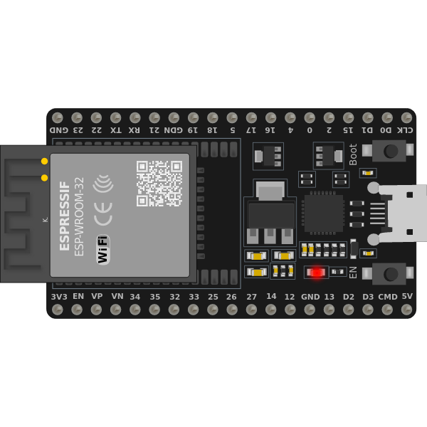
Pin Configuration and Descriptions
The ESP32 has multiple GPIO pins, which are multiplexed with various functions. Below is a table of commonly used pins and their descriptions:
| Pin Name | Function(s) | Description |
|---|---|---|
| GPIO0 | Input, Boot Mode Selection | Used for boot mode selection during startup. |
| GPIO2 | Input/Output, ADC, DAC | General-purpose pin with ADC/DAC capabilities. |
| GPIO4 | Input/Output, ADC, PWM | General-purpose pin with ADC and PWM support. |
| GPIO5 | Input/Output, ADC, PWM | General-purpose pin with ADC and PWM support. |
| GPIO12 | Input/Output, ADC, Touch Sensor | Supports touch sensing and ADC functionality. |
| GPIO13 | Input/Output, ADC, Touch Sensor | Supports touch sensing and ADC functionality. |
| GPIO14 | Input/Output, ADC, PWM | General-purpose pin with ADC and PWM support. |
| GPIO15 | Input/Output, ADC, Touch Sensor | Supports touch sensing and ADC functionality. |
| GPIO16 | Input/Output | General-purpose pin. |
| GPIO17 | Input/Output | General-purpose pin. |
| EN | Enable | Used to enable or reset the chip. |
| VIN | Power Input | Connect to 5V power supply. |
| GND | Ground | Connect to ground. |
Note: Some GPIO pins have specific restrictions or are used during boot. Refer to the ESP32 datasheet for detailed pin behavior.
Usage Instructions
How to Use the ESP32 in a Circuit
Powering the ESP32:
- The ESP32 operates at 3.3V. Use a voltage regulator if your power source exceeds this voltage.
- Connect the VIN pin to a 5V power source and GND to ground.
Programming the ESP32:
- The ESP32 can be programmed using the Arduino IDE or Espressif's ESP-IDF framework.
- Connect the ESP32 to your computer via a USB-to-serial adapter or a development board with built-in USB support.
- Install the necessary drivers and libraries for your chosen development environment.
Connecting Peripherals:
- Use GPIO pins to connect sensors, actuators, or other peripherals.
- Ensure that the voltage levels of connected devices are compatible with the ESP32's 3.3V logic.
Uploading Code:
- Write your code in the Arduino IDE or ESP-IDF.
- Select the correct board and port in the IDE.
- Press the "Upload" button to flash the code to the ESP32.
Important Considerations and Best Practices
- Avoid connecting 5V logic devices directly to the GPIO pins; use level shifters if needed.
- Use pull-up or pull-down resistors for input pins to prevent floating states.
- Be cautious with GPIO0, GPIO2, and GPIO15, as they affect the boot process.
- Use decoupling capacitors near the power pins to stabilize the power supply.
Example Code for Arduino IDE
Below is an example of how to blink an LED connected to GPIO2:
// Define the GPIO pin for the LED
#define LED_PIN 2

void setup() {
  // Set the LED pin as an output
  pinMode(LED_PIN, OUTPUT);
}

void loop() {
  // Turn the LED on
  digitalWrite(LED_PIN, HIGH);
  delay(1000); // Wait for 1 second

  // Turn the LED off
  digitalWrite(LED_PIN, LOW);
  delay(1000); // Wait for 1 second
}
Note: Ensure that the LED is connected to GPIO2 with a current-limiting resistor (e.g., 220Ω) to prevent damage.
Troubleshooting and FAQs
Common Issues and Solutions
ESP32 Not Detected by Computer:
- Ensure the USB cable is functional and supports data transfer.
- Install the correct USB-to-serial driver for your development board.
Code Upload Fails:
- Check the selected board and port in the Arduino IDE.
- Press and hold the "BOOT" button on the ESP32 board while uploading.
Wi-Fi Connection Issues:
- Verify the SSID and password in your code.
- Ensure the Wi-Fi network is within range and supports 2.4 GHz (ESP32 does not support 5 GHz).
Random Resets or Instability:
- Check the power supply for sufficient current (at least 500 mA).
- Add decoupling capacitors to stabilize the power supply.
FAQs
Q: Can the ESP32 operate on battery power?
A: Yes, the ESP32 can be powered by batteries. Use a 3.7V LiPo battery with a voltage regulator or a 5V power bank.
Q: How do I use Bluetooth on the ESP32?
A: The ESP32 supports both Bluetooth Classic and BLE. Use the BluetoothSerial or BLE libraries in the Arduino IDE to implement Bluetooth functionality.
Q: Can I use the ESP32 with 5V sensors?
A: Directly connecting 5V sensors to the ESP32 is not recommended. Use a level shifter to convert the voltage to 3.3V.
Q: What is the maximum range of the ESP32's Wi-Fi?
A: The Wi-Fi range depends on the environment but typically extends up to 100 meters in open spaces.