How to Use Pololu RC Switch with Digital Output: Examples, Pinouts, and Specs
Introduction
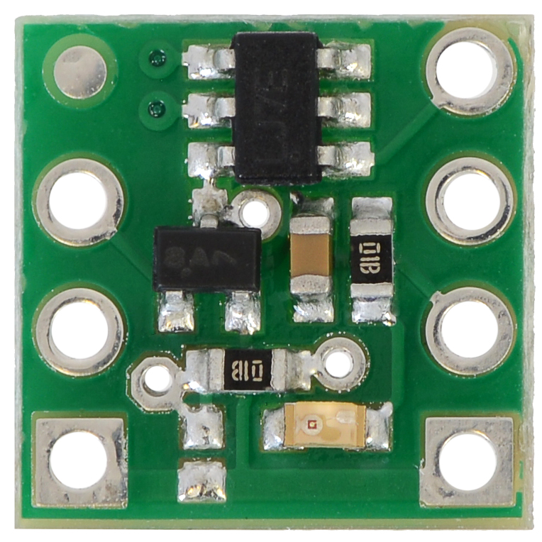
The Pololu RC Switch with Digital Output (Part ID: 2801) is a versatile remote control switch designed for wireless control of devices. It features a digital output, making it easy to integrate with microcontrollers, such as Arduino, and other electronic systems. This component is ideal for applications requiring remote activation or deactivation of devices, such as robotics, RC vehicles, and home automation systems.
Explore Projects Built with Pololu RC Switch with Digital Output

Explore Projects Built with Pololu RC Switch with Digital Output
Common Applications
- Wireless control of LEDs, motors, or relays
- Integration with RC receivers for remote operation
- Robotics and automation projects
- Home automation systems
- Prototyping and testing of remote-controlled devices
Technical Specifications
The following table outlines the key technical details of the Pololu RC Switch with Digital Output:
| Parameter | Value |
|---|---|
| Operating Voltage | 2.5 V to 5.5 V |
| Digital Output Voltage | Matches the operating voltage (logic level) |
| Maximum Output Current | 25 mA |
| Input Signal Range | 3.0 V to 5.0 V (compatible with RC receivers) |
| Input Signal Frequency | 10 Hz to 333 Hz |
| Dimensions | 0.6" × 0.8" × 0.1" (15 mm × 20 mm × 3 mm) |
| Weight | 0.5 g |
Pin Configuration and Descriptions
The Pololu RC Switch has six pins, as described in the table below:
| Pin Name | Description |
|---|---|
| VCC | Power supply input (2.5 V to 5.5 V). Connect to the positive terminal of the power source. |
| GND | Ground connection. Connect to the negative terminal of the power source. |
| RC IN | Input pin for the RC signal. Connect to the signal pin of the RC receiver. |
| OUT | Digital output pin. Provides a high or low signal based on the RC input. |
| AUX | Auxiliary output pin. Can be used for additional functionality. |
| SEL | Selection pin for configuring the behavior of the switch. |
Usage Instructions
How to Use the Component in a Circuit
- Power the RC Switch: Connect the
VCCpin to a power source (2.5 V to 5.5 V) and theGNDpin to ground. - Connect the RC Receiver: Attach the
RC INpin to the signal output of your RC receiver. - Connect the Output Device: Use the
OUTpin to control your device (e.g., an LED, relay, or microcontroller input pin). - Configure the Behavior: Use the
SELpin to adjust the switch's behavior, such as the threshold for activation or fail-safe settings.
Important Considerations and Best Practices
- Ensure the operating voltage of the RC switch matches the voltage of your system.
- Do not exceed the maximum output current of 25 mA on the
OUTpin. - Use a pull-down resistor on the
OUTpin if the connected device requires a stable low state when the switch is off. - For microcontroller integration, ensure the logic levels of the RC switch are compatible with the microcontroller's input pins.
Example: Connecting to an Arduino UNO
The following example demonstrates how to use the Pololu RC Switch with an Arduino UNO to control an LED based on the RC signal.
Circuit Connections
- Connect the
VCCpin of the RC switch to the Arduino's5Vpin. - Connect the
GNDpin of the RC switch to the Arduino'sGNDpin. - Connect the
RC INpin to the signal output of the RC receiver. - Connect the
OUTpin to a digital input pin on the Arduino (e.g.,D2). - Connect an LED to another digital pin (e.g.,
D13) with a current-limiting resistor.
Arduino Code
// Define the pin connected to the RC switch's OUT pin
const int rcSwitchPin = 2;

// Define the pin connected to the LED
const int ledPin = 13;

void setup() {
  // Initialize the RC switch pin as an input
  pinMode(rcSwitchPin, INPUT);

  // Initialize the LED pin as an output
  pinMode(ledPin, OUTPUT);

  // Start the serial communication for debugging
  Serial.begin(9600);
}

void loop() {
  // Read the state of the RC switch
  int switchState = digitalRead(rcSwitchPin);

  // Print the switch state to the serial monitor
  Serial.print("RC Switch State: ");
  Serial.println(switchState);

  // Control the LED based on the switch state
  if (switchState == HIGH) {
    digitalWrite(ledPin, HIGH); // Turn on the LED
  } else {
    digitalWrite(ledPin, LOW);  // Turn off the LED
  }

  // Add a small delay for stability
  delay(100);
}
Troubleshooting and FAQs
Common Issues and Solutions
The RC switch does not respond to the RC signal.
- Verify that the
RC INpin is properly connected to the RC receiver's signal output. - Ensure the RC receiver is powered and functioning correctly.
- Check that the input signal frequency is within the supported range (10 Hz to 333 Hz).
- Verify that the
The output pin does not change state.
- Confirm that the
OUTpin is connected to the correct input of the device or microcontroller. - Ensure the RC signal meets the required voltage range (3.0 V to 5.0 V).
- Check the configuration of the
SELpin to ensure the desired behavior is set.
- Confirm that the
The connected device does not operate as expected.
- Verify that the device's voltage and current requirements are within the RC switch's output capabilities.
- Use a pull-down resistor on the
OUTpin if the connected device requires a stable low state.
FAQs
Q: Can the RC switch be used with a 3.3 V system?
A: Yes, the RC switch operates within a voltage range of 2.5 V to 5.5 V, making it compatible with 3.3 V systems.
Q: What happens if the RC signal is lost?
A: The behavior of the RC switch in the event of signal loss depends on the configuration of the SEL pin. Refer to the Pololu documentation for detailed configuration options.
Q: Can I use the RC switch to control a motor directly?
A: No, the RC switch's output current is limited to 25 mA. To control a motor, use the RC switch to drive a motor driver or relay.
Q: Is the RC switch compatible with all RC receivers?
A: The RC switch is compatible with most RC receivers that output a signal within the 3.0 V to 5.0 V range and a frequency of 10 Hz to 333 Hz.