Cirkit Designer Logo
Cirkit Designer
Your all-in-one circuit design IDE
Home / 
Component Documentation

How to Use esp32 s2 devkitc-1: Examples, Pinouts, and Specs

Image of esp32 s2 devkitc-1
Cirkit Designer LogoDesign with esp32 s2 devkitc-1 in Cirkit Designer

Introduction

The ESP32-S2-DevKitC-1 is a development board manufactured by Espressif. It is built around the ESP32-S2 chip, which features a single-core Xtensa® LX7 processor, integrated Wi-Fi, and a rich set of peripherals. This board is designed for IoT (Internet of Things) applications, offering a cost-effective and versatile platform for prototyping and development.

Explore Projects Built with esp32 s2 devkitc-1

Use Cirkit Designer to design, explore, and prototype these projects online. Some projects support real-time simulation. Click "Open Project" to start designing instantly!
ESP32-Based Environmental Monitoring and Alert System with Solar Charging
Image of mark: A project utilizing esp32 s2 devkitc-1 in a practical application
This circuit features an ESP32 Devkit V1 microcontroller connected to various sensors and modules for monitoring and communication purposes. It includes an MQ-2 gas sensor and a DHT11 temperature and humidity sensor, both interfaced with the ESP32 for environmental data collection. The circuit is powered by a 12V battery, regulated to 5V by step-down converters, and includes a solar charge controller connected to a solar panel for battery charging, a UPS module for power management, and a SIM900A module for GSM communication. Additionally, there is a WS2812 RGB LED strip for visual feedback and a piezo buzzer for audio alerts, both controlled by the ESP32.
Cirkit Designer LogoOpen Project in Cirkit Designer
ESP32-S3 GPS and Wind Speed Logger with Dual OLED Displays and CAN Bus
Image of esp32-s3-ellipse: A project utilizing esp32 s2 devkitc-1 in a practical application
This circuit features an ESP32-S3 microcontroller interfaced with an SD card module, two OLED displays, a GPS module, and a CAN bus module. The ESP32-S3 records GPS data to the SD card, displays speed on one OLED, and shows wind speed from the CAN bus on the other OLED, providing a comprehensive data logging and display system.
Cirkit Designer LogoOpen Project in Cirkit Designer
ESP32-Based Automated Hydroponic System Controller
Image of SHy-WickS: A project utilizing esp32 s2 devkitc-1 in a practical application
This circuit features an ESP32 Devkit V1 microcontroller connected to various sensors and devices for environmental monitoring and control. It includes a DHT11 for temperature and humidity sensing, a PH sensor, a TDS (Total Dissolved Solids) sensor, and an HC-SR04 ultrasonic sensor, likely for liquid level measurement. The ESP32 controls two 5V mini water pumps via a 2-channel relay module, and displays data on multiple I2C LCD screens.
Cirkit Designer LogoOpen Project in Cirkit Designer
ESP32-Based Environmental Monitoring and Alert System with Solar Charging
Image of Schematic: A project utilizing esp32 s2 devkitc-1 in a practical application
This circuit features an ESP32 Devkit V1 microcontroller connected to various sensors and devices, including a DHT11 temperature and humidity sensor, an MQ-2 gas sensor, and a WS2812 RGB LED strip. The ESP32 controls the LED strip and processes sensor readings, while a SIM900A module provides cellular communication capabilities. Power management is handled by a UPS module fed by a 12V battery charged via a solar panel and charge controller, with voltage regulation provided by step-down converters. Additionally, a piezo buzzer is included for audible alerts, and the system's safety is ensured by a circuit breaker connected to a switching power supply for AC to DC conversion.
Cirkit Designer LogoOpen Project in Cirkit Designer

Explore Projects Built with esp32 s2 devkitc-1

Use Cirkit Designer to design, explore, and prototype these projects online. Some projects support real-time simulation. Click "Open Project" to start designing instantly!
Image of mark: A project utilizing esp32 s2 devkitc-1 in a practical application
ESP32-Based Environmental Monitoring and Alert System with Solar Charging
This circuit features an ESP32 Devkit V1 microcontroller connected to various sensors and modules for monitoring and communication purposes. It includes an MQ-2 gas sensor and a DHT11 temperature and humidity sensor, both interfaced with the ESP32 for environmental data collection. The circuit is powered by a 12V battery, regulated to 5V by step-down converters, and includes a solar charge controller connected to a solar panel for battery charging, a UPS module for power management, and a SIM900A module for GSM communication. Additionally, there is a WS2812 RGB LED strip for visual feedback and a piezo buzzer for audio alerts, both controlled by the ESP32.
Cirkit Designer LogoOpen Project in Cirkit Designer
Image of esp32-s3-ellipse: A project utilizing esp32 s2 devkitc-1 in a practical application
ESP32-S3 GPS and Wind Speed Logger with Dual OLED Displays and CAN Bus
This circuit features an ESP32-S3 microcontroller interfaced with an SD card module, two OLED displays, a GPS module, and a CAN bus module. The ESP32-S3 records GPS data to the SD card, displays speed on one OLED, and shows wind speed from the CAN bus on the other OLED, providing a comprehensive data logging and display system.
Cirkit Designer LogoOpen Project in Cirkit Designer
Image of SHy-WickS: A project utilizing esp32 s2 devkitc-1 in a practical application
ESP32-Based Automated Hydroponic System Controller
This circuit features an ESP32 Devkit V1 microcontroller connected to various sensors and devices for environmental monitoring and control. It includes a DHT11 for temperature and humidity sensing, a PH sensor, a TDS (Total Dissolved Solids) sensor, and an HC-SR04 ultrasonic sensor, likely for liquid level measurement. The ESP32 controls two 5V mini water pumps via a 2-channel relay module, and displays data on multiple I2C LCD screens.
Cirkit Designer LogoOpen Project in Cirkit Designer
Image of Schematic: A project utilizing esp32 s2 devkitc-1 in a practical application
ESP32-Based Environmental Monitoring and Alert System with Solar Charging
This circuit features an ESP32 Devkit V1 microcontroller connected to various sensors and devices, including a DHT11 temperature and humidity sensor, an MQ-2 gas sensor, and a WS2812 RGB LED strip. The ESP32 controls the LED strip and processes sensor readings, while a SIM900A module provides cellular communication capabilities. Power management is handled by a UPS module fed by a 12V battery charged via a solar panel and charge controller, with voltage regulation provided by step-down converters. Additionally, a piezo buzzer is included for audible alerts, and the system's safety is ensured by a circuit breaker connected to a switching power supply for AC to DC conversion.
Cirkit Designer LogoOpen Project in Cirkit Designer

Common Applications and Use Cases

  • IoT devices and smart home applications
  • Wireless sensor networks
  • Industrial automation
  • Wearable devices
  • Low-power applications requiring Wi-Fi connectivity
  • Prototyping for embedded systems

Technical Specifications

The following are the key technical details of the ESP32-S2-DevKitC-1:

Specification Details
Chip ESP32-S2 (Xtensa® LX7 single-core processor)
Wi-Fi 802.11 b/g/n (2.4 GHz)
Flash Memory 4 MB (default, may vary by model)
SRAM 320 KB (internal) + 128 KB (ROM)
Operating Voltage 3.3 V
GPIO Pins 37 GPIOs (multiplexed with other functions)
ADC Channels 14 channels (12-bit resolution)
Interfaces SPI, I2C, I2S, UART, PWM, RMT, USB OTG
USB Connectivity Full-speed USB OTG (On-The-Go)
Power Supply 5 V via USB or external 3.3 V supply
Operating Temperature -40°C to +85°C
Dimensions 52 mm x 25 mm

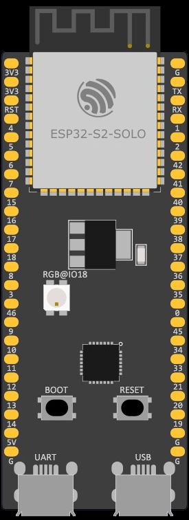
Pin Configuration and Descriptions

The ESP32-S2-DevKitC-1 features a dual-row header with the following pinout:

Pin Name Function
1 3V3 3.3 V power output
2 GND Ground
3 GPIO0 General-purpose I/O, boot mode selection
4 GPIO1 General-purpose I/O
5 GPIO2 General-purpose I/O
6 GPIO3 General-purpose I/O
7 GPIO4 General-purpose I/O
8 GPIO5 General-purpose I/O
9 EN Chip enable (active high)
10 IOREF Reference voltage for I/O
11 ADC1_CH0 Analog input channel 0
12 ADC1_CH1 Analog input channel 1
... ... ... (Refer to the official datasheet for the full pinout)

Note: Some GPIO pins are multiplexed with other functions (e.g., ADC, UART). Refer to the ESP32-S2 datasheet for detailed pin capabilities.

Usage Instructions

How to Use the ESP32-S2-DevKitC-1 in a Circuit

  1. Powering the Board:

    • Connect the board to a computer or USB power source using a micro-USB cable.
    • Alternatively, supply 3.3 V directly to the 3V3 pin and GND to the GND pin.
  2. Programming the Board:

    • Install the Arduino IDE or Espressif IDF (IoT Development Framework).
    • Add the ESP32-S2 board support package to your development environment.
    • Connect the board to your computer via USB and select the appropriate COM port.
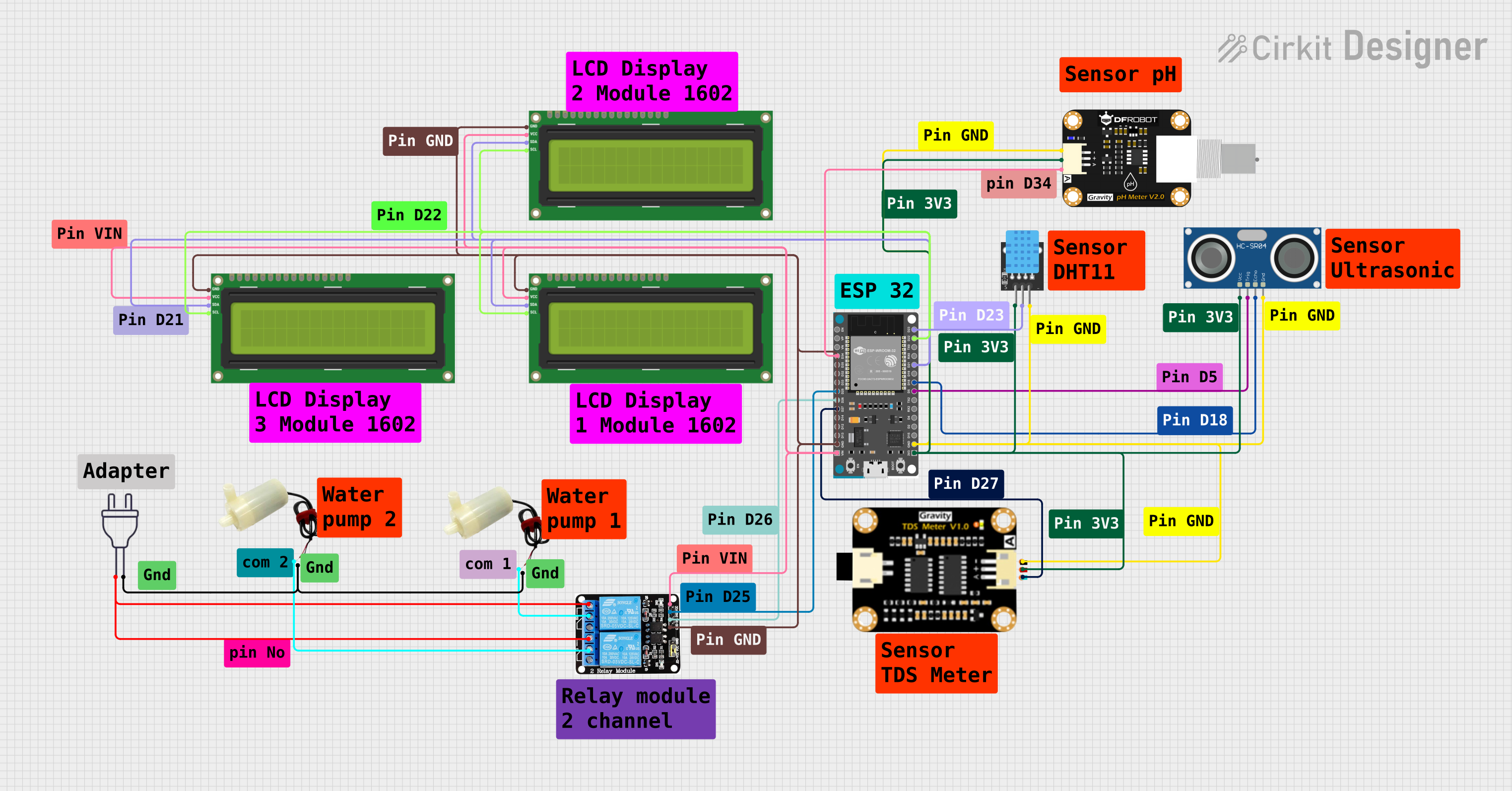
  3. Connecting Peripherals:

    • Use the GPIO pins to connect sensors, actuators, or other peripherals.
    • Ensure that the voltage levels of connected devices are compatible with the 3.3 V logic of the ESP32-S2.
  4. Flashing Code:

    • Write your code in the Arduino IDE or Espressif IDF.
    • Compile and upload the code to the board.
    • Use the serial monitor to debug or view output.

Example: Blinking an LED with Arduino IDE

The following example demonstrates how to blink an LED connected to GPIO2:

// Define the GPIO pin where the LED is connected
#define LED_PIN 2

void setup() {
  // Set the LED pin as an output
  pinMode(LED_PIN, OUTPUT);
}

void loop() {
  // Turn the LED on
  digitalWrite(LED_PIN, HIGH);
  delay(1000); // Wait for 1 second

  // Turn the LED off
  digitalWrite(LED_PIN, LOW);
  delay(1000); // Wait for 1 second
}

Important Considerations and Best Practices

  • Voltage Levels: Ensure all connected peripherals operate at 3.3 V logic levels. Use level shifters if necessary.
  • Boot Mode: GPIO0 is used for boot mode selection. Avoid pulling it high during boot if not required.
  • Power Supply: Use a stable power source to avoid unexpected resets or malfunctions.
  • USB OTG: If using USB OTG functionality, ensure proper configuration in the firmware.

Troubleshooting and FAQs

Common Issues and Solutions

  1. Board Not Detected by Computer:

    • Ensure the USB cable is functional and supports data transfer.
    • Install the correct USB-to-serial driver for the ESP32-S2.
  2. Code Fails to Upload:

    • Check that the correct COM port is selected in the IDE.
    • Hold the BOOT button while pressing the EN button to enter flashing mode.
  3. Wi-Fi Connection Issues:

    • Verify the SSID and password in your code.
    • Ensure the Wi-Fi network operates on the 2.4 GHz band (not 5 GHz).
  4. GPIO Pin Not Working:

    • Confirm the pin is not being used for another function (e.g., ADC, UART).
    • Check for proper wiring and connections.

FAQs

Q: Can I use the ESP32-S2-DevKitC-1 with MicroPython?
A: Yes, the ESP32-S2 supports MicroPython. Flash the MicroPython firmware to the board and use a serial terminal or IDE like Thonny.

Q: What is the maximum current output of the 3V3 pin?
A: The 3V3 pin can supply up to 500 mA, depending on the input power source.

Q: Does the ESP32-S2 support Bluetooth?
A: No, the ESP32-S2 only supports Wi-Fi. For Bluetooth functionality, consider the ESP32 or ESP32-C3 series.

Q: How do I reset the board?
A: Press the EN button to reset the board.

For more detailed information, refer to the official Espressif ESP32-S2-DevKitC-1 datasheet.