Cirkit Designer Logo
Cirkit Designer
Your all-in-one circuit design IDE
Home / 
Component Documentation

How to Use raspberry pi pico w: Examples, Pinouts, and Specs

Image of raspberry pi pico w
Cirkit Designer LogoDesign with raspberry pi pico w in Cirkit Designer

Introduction

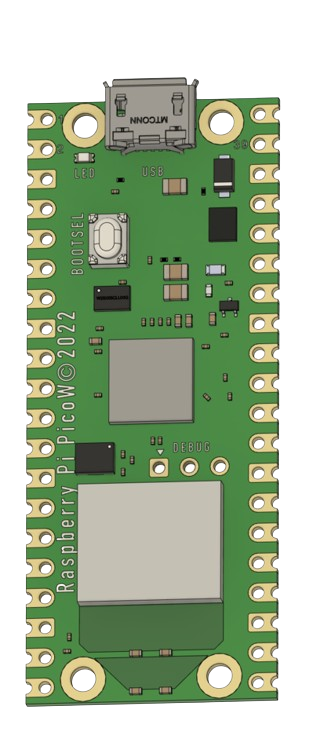
The Raspberry Pi Pico W is a compact and affordable microcontroller board that extends the capabilities of the original Raspberry Pi Pico by adding wireless connectivity. It is based on the Raspberry Pi RP2040 microcontroller chip and is designed for a wide range of applications, from IoT devices and home automation to educational projects and prototyping. The Pico W's Wi-Fi feature enables it to connect to the internet or local networks, making it a versatile choice for wireless projects.

Explore Projects Built with raspberry pi pico w

Use Cirkit Designer to design, explore, and prototype these projects online. Some projects support real-time simulation. Click "Open Project" to start designing instantly!
Wi-Fi Controlled RGB Lighting with Raspberry Pi Pico W
Image of Smart Home Automation 1: A project utilizing raspberry pi pico w in a practical application
This circuit features a Raspberry Pi Pico W microcontroller connected to an RGB LED through GPIO pins GP17, GP18, and GP19 for controlling the blue, green, and red channels, respectively. A resistor is connected between the 3V3 OUT pin of the Pico and the common cathode of the RGB LED to limit the current. The embedded code suggests the Pico W is configured for Wi-Fi connectivity and MQTT communication to control the LED and possibly other peripherals not shown in the circuit, with additional functionality for sensor monitoring and display output.
Cirkit Designer LogoOpen Project in Cirkit Designer
Raspberry Pi Pico W-Based Smart Home Automation System with Motion Detection and Environmental Monitoring
Image of Smart Home Automation 1: A project utilizing raspberry pi pico w in a practical application
This circuit features a Raspberry Pi Pico W microcontroller connected to various sensors and actuators, including a DHT11 temperature and humidity sensor, an RCWL-0516 microwave radar motion sensor, a photocell (LDR) with a resistor for light detection, and a two-channel relay controlling a bulb and a fan. The microcontroller runs code to monitor environmental conditions and motion, displaying information on an LCD and allowing remote control via MQTT messages over Wi-Fi. It supports both automatic sensor-based operation and remote app control, with pushbuttons to switch between modes.
Cirkit Designer LogoOpen Project in Cirkit Designer
Raspberry Pi Pico W RGB LED Controller with Resistors
Image of RGB LED: A project utilizing raspberry pi pico w in a practical application
This circuit uses a Raspberry Pi Pico W to control an RGB LED through three 220-ohm resistors connected to its GPIO pins. The Pico W provides 3.3V power to the common anode of the RGB LED, allowing for color control via the GPIO pins GP13, GP14, and GP15.
Cirkit Designer LogoOpen Project in Cirkit Designer
Raspberry Pi Pico and ESP32 Wi-Fi Controlled Sensor Interface
Image of pico_esp32: A project utilizing raspberry pi pico w in a practical application
This circuit integrates a Raspberry Pi Pico and an ESP32 Wroom Dev Kit, interconnected through various GPIO pins and resistors, to enable communication and control between the two microcontrollers. The ESP32 is powered by a 3.3V supply and shares ground with the Raspberry Pi Pico, while specific GPIO pins are used for data exchange. The provided code sketches for the Raspberry Pi Pico suggest a framework for further development of the system's functionality.
Cirkit Designer LogoOpen Project in Cirkit Designer

Explore Projects Built with raspberry pi pico w

Use Cirkit Designer to design, explore, and prototype these projects online. Some projects support real-time simulation. Click "Open Project" to start designing instantly!
Image of Smart Home Automation 1: A project utilizing raspberry pi pico w in a practical application
Wi-Fi Controlled RGB Lighting with Raspberry Pi Pico W
This circuit features a Raspberry Pi Pico W microcontroller connected to an RGB LED through GPIO pins GP17, GP18, and GP19 for controlling the blue, green, and red channels, respectively. A resistor is connected between the 3V3 OUT pin of the Pico and the common cathode of the RGB LED to limit the current. The embedded code suggests the Pico W is configured for Wi-Fi connectivity and MQTT communication to control the LED and possibly other peripherals not shown in the circuit, with additional functionality for sensor monitoring and display output.
Cirkit Designer LogoOpen Project in Cirkit Designer
Image of Smart Home Automation 1: A project utilizing raspberry pi pico w in a practical application
Raspberry Pi Pico W-Based Smart Home Automation System with Motion Detection and Environmental Monitoring
This circuit features a Raspberry Pi Pico W microcontroller connected to various sensors and actuators, including a DHT11 temperature and humidity sensor, an RCWL-0516 microwave radar motion sensor, a photocell (LDR) with a resistor for light detection, and a two-channel relay controlling a bulb and a fan. The microcontroller runs code to monitor environmental conditions and motion, displaying information on an LCD and allowing remote control via MQTT messages over Wi-Fi. It supports both automatic sensor-based operation and remote app control, with pushbuttons to switch between modes.
Cirkit Designer LogoOpen Project in Cirkit Designer
Image of RGB LED: A project utilizing raspberry pi pico w in a practical application
Raspberry Pi Pico W RGB LED Controller with Resistors
This circuit uses a Raspberry Pi Pico W to control an RGB LED through three 220-ohm resistors connected to its GPIO pins. The Pico W provides 3.3V power to the common anode of the RGB LED, allowing for color control via the GPIO pins GP13, GP14, and GP15.
Cirkit Designer LogoOpen Project in Cirkit Designer
Image of pico_esp32: A project utilizing raspberry pi pico w in a practical application
Raspberry Pi Pico and ESP32 Wi-Fi Controlled Sensor Interface
This circuit integrates a Raspberry Pi Pico and an ESP32 Wroom Dev Kit, interconnected through various GPIO pins and resistors, to enable communication and control between the two microcontrollers. The ESP32 is powered by a 3.3V supply and shares ground with the Raspberry Pi Pico, while specific GPIO pins are used for data exchange. The provided code sketches for the Raspberry Pi Pico suggest a framework for further development of the system's functionality.
Cirkit Designer LogoOpen Project in Cirkit Designer

Technical Specifications

Key Features

  • Microcontroller: RP2040 by Raspberry Pi
  • Wi-Fi: 2.4 GHz 802.11n wireless LAN
  • RAM: 264KB on-chip SRAM
  • Flash Memory: 2MB on-board QSPI Flash
  • GPIO Pins: 26 multi-function GPIO pins
  • Clock Speed: Dual-core Arm Cortex-M0+ processor, up to 133 MHz
  • Power Supply: 5V via micro-USB port or external source
  • Operating Temperature: -20°C to +85°C

Pin Configuration

Pin Number Name Description
1 3V3 3.3V Power Output
2 GP0 GPIO 0 / SPI RX
3 GP1 GPIO 1 / SPI CS
... ... ...
40 GND Ground

Note: This is a partial representation of the pin configuration. Refer to the official datasheet for the complete pinout.

Usage Instructions

Setting Up the Raspberry Pi Pico W

  1. Power Supply: Connect the micro-USB cable to the Pico W and to a 5V USB power source.
  2. Programming: Use the onboard micro-USB port to program the Pico W with software like Thonny or the Raspberry Pi Pico Python SDK.
  3. Connecting to Wi-Fi: Utilize the onboard wireless LAN to connect to a Wi-Fi network for internet access or local network communication.

Best Practices

  • ESD Precautions: Always handle the Pico W with proper electrostatic discharge precautions.
  • Power Ratings: Do not exceed the recommended voltage levels on any of the I/O pins to prevent damage.
  • Wi-Fi Antenna: Ensure that the Wi-Fi antenna area is not obstructed to maintain good signal strength.

Example Code for Wi-Fi Connection

import network
import socket

Initialize Wi-Fi

wlan = network.WLAN(network.STA_IF) wlan.active(True) wlan.connect('your-ssid', 'your-password')

Check if connected

if wlan.isconnected(): print("Connected to Wi-Fi") else: print("Connection failed")

Create a socket and connect to a server

addr_info = socket.getaddrinfo("www.example.com", 80) addr = addr_info[0][-1] s = socket.socket() s.connect(addr)

Send a request and receive a response

s.send(b"GET / HTTP/1.1\r\nHost: www.example.com\r\n\r\n") response = s.recv(1000) print(response)

Close the socket

s.close()


*Note: Replace 'your-ssid' and 'your-password' with your actual Wi-Fi credentials.*

Troubleshooting and FAQs

Common Issues

  • Wi-Fi Not Connecting: Ensure the SSID and password are correct. Check the signal strength and the proximity to the router.
  • No Power: Verify that the micro-USB cable is properly connected and the power source is supplying 5V.
  • Not Recognized by Computer: Make sure the micro-USB cable is data-capable and the Pico W is in BOOTSEL mode if necessary.

FAQs

Q: How do I reset the Pico W? A: Briefly short the RUN pin to GND or power cycle the board.

Q: Can I use the Pico W with Arduino IDE? A: Yes, with the appropriate board support package installed.

Q: What is the maximum current draw from the 3V3 pin? A: The maximum current draw from the 3V3 pin should not exceed 300 mA.

For further assistance, consult the Raspberry Pi forums and the official Raspberry Pi Pico W documentation.