Cirkit Designer
Your all-in-one circuit design IDE
Home /
Component Documentation
How to Use UPSs: Examples, Pinouts, and Specs

Introduction
The THESIS FIRST UPSs is an Uninterruptible Power Supply designed to provide emergency power to critical systems when the main power source fails. This component ensures that computers, data centers, and other sensitive electronic equipment continue to operate during short-term power outages or fluctuations, preventing data loss and hardware damage. Common applications include safeguarding servers, networking devices, and telecommunications systems.
Explore Projects Built with UPSs
12V UPS System with Dual 18650 Li-ion Battery Backup and Voltage Regulation

This circuit is designed to provide an uninterruptible power supply (UPS) system with a 12V DC output. It includes a 12V 5A power supply connected to an AC source through a toggle switch, which charges a pair of 18650 Li-ion batteries via a voltage regulator (XL4016). The UPS module ensures a continuous power supply to the load by switching between the power supply and the battery bank.
Battery-Powered UPS with Step-Down Buck Converter and BMS

This circuit is a power management system that steps down a 240V AC input to a lower DC voltage using a buck converter, which then powers a 40W UPS. The UPS is controlled by a rocker switch and is backed up by a battery management system (BMS) connected to three 3.7V batteries in series, ensuring continuous power supply.
Solar-Powered UPS with Dual Step-Down Converters and ESP32 Control
This circuit is designed to provide a stable power supply from various sources. It integrates a solar panel with a solar charge controller to charge a 12V battery, which is then connected to a UPS module for regulated output. The circuit also includes two 12v to 5v step-down power converters to supply 5V power, one of which powers an ESP32 Devkit V1 microcontroller, and a switching power supply to provide an alternative AC to DC conversion input to the UPS module.
Solar-Powered ESP32 IoT Device with UPS Battery Backup and AC Integration
This is a solar power management system with a microcontroller-based control unit. It includes a solar panel connected to a charge controller that charges a UPS battery, with an automatic transfer switch to alternate between solar and AC mains power. Protection is ensured by diodes and fuses, and a buck converter regulates the voltage for the ESP32 microcontroller.
Explore Projects Built with UPSs
12V UPS System with Dual 18650 Li-ion Battery Backup and Voltage Regulation
This circuit is designed to provide an uninterruptible power supply (UPS) system with a 12V DC output. It includes a 12V 5A power supply connected to an AC source through a toggle switch, which charges a pair of 18650 Li-ion batteries via a voltage regulator (XL4016). The UPS module ensures a continuous power supply to the load by switching between the power supply and the battery bank.
Battery-Powered UPS with Step-Down Buck Converter and BMS
This circuit is a power management system that steps down a 240V AC input to a lower DC voltage using a buck converter, which then powers a 40W UPS. The UPS is controlled by a rocker switch and is backed up by a battery management system (BMS) connected to three 3.7V batteries in series, ensuring continuous power supply.
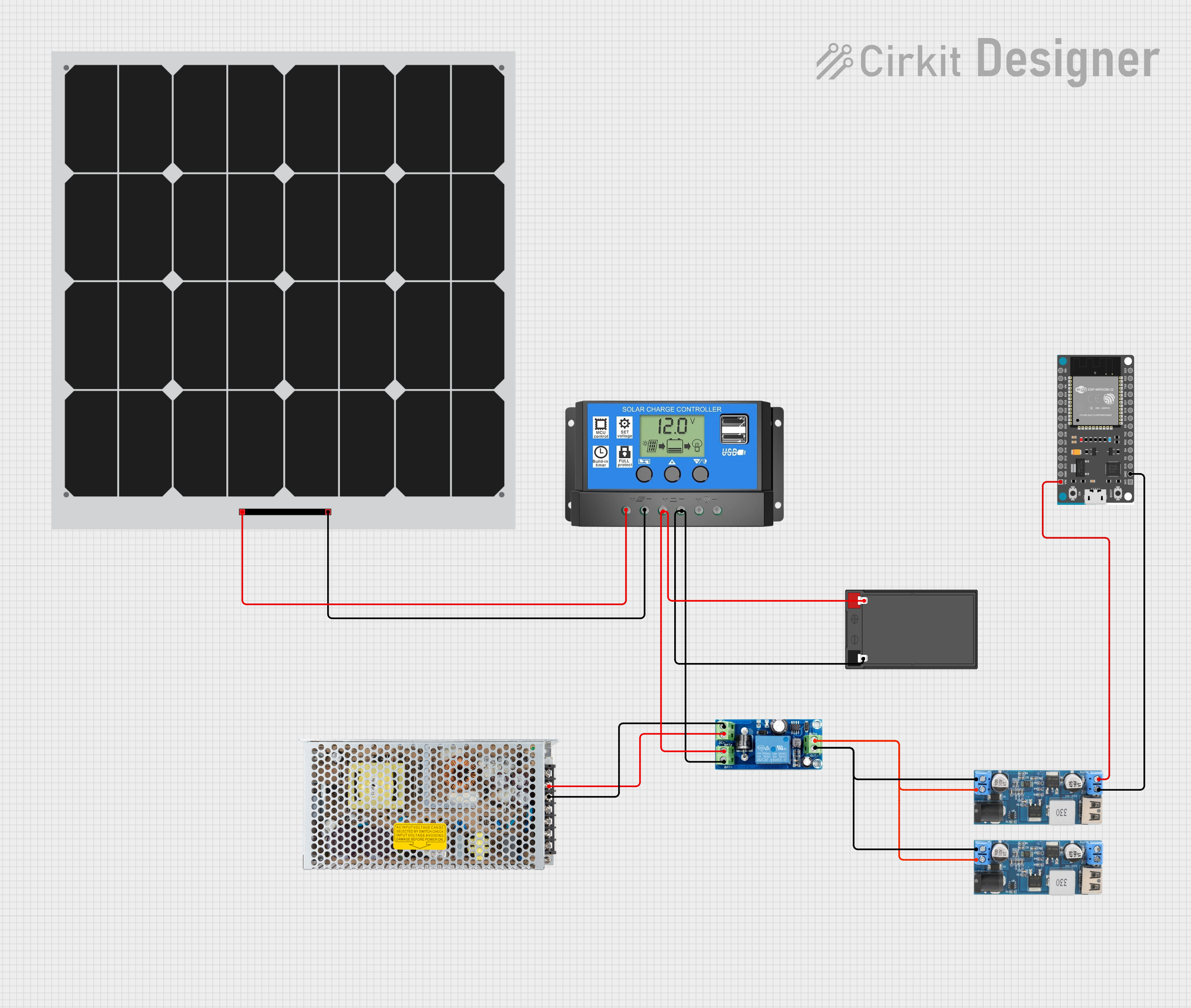
Solar-Powered UPS with Dual Step-Down Converters and ESP32 Control
This circuit is designed to provide a stable power supply from various sources. It integrates a solar panel with a solar charge controller to charge a 12V battery, which is then connected to a UPS module for regulated output. The circuit also includes two 12v to 5v step-down power converters to supply 5V power, one of which powers an ESP32 Devkit V1 microcontroller, and a switching power supply to provide an alternative AC to DC conversion input to the UPS module.
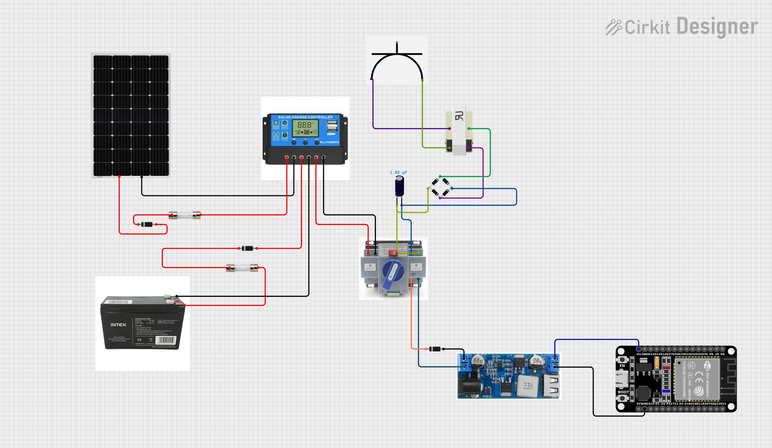
Solar-Powered ESP32 IoT Device with UPS Battery Backup and AC Integration
This is a solar power management system with a microcontroller-based control unit. It includes a solar panel connected to a charge controller that charges a UPS battery, with an automatic transfer switch to alternate between solar and AC mains power. Protection is ensured by diodes and fuses, and a buck converter regulates the voltage for the ESP32 microcontroller.
Technical Specifications
General Specifications
| Specification | Value/Description |
|---|---|
| Input Voltage Range | 110-240V AC |
| Output Voltage | 110-240V AC (configurable) |
| Frequency | 50/60 Hz (auto-sensing) |
| Battery Type | Sealed Lead-Acid / Lithium-ion (model dependent) |
| Typical Backup Time | 5-30 minutes (load dependent) |
| Communication Interface | USB, RS232, SNMP (optional) |
| Efficiency | Up to 95% |
| Operating Temperature | 0°C to 40°C |
Pin Configuration and Descriptions
| Pin Number | Description | Notes |
|---|---|---|
| 1 | AC Input | Connect to main power source |
| 2 | AC Output | Connect to load (equipment to protect) |
| 3 | Ground | Safety ground connection |
| 4 | USB Communication Port | For monitoring and configuration |
| 5 | RS232 Communication Port | For monitoring and configuration |
| 6 | SNMP Slot | Optional for network-based management |
| 7 | Battery Connector | Connects internal battery pack |
| 8 | External Battery Connector | For additional battery packs (if supported) |
Usage Instructions
Installation
- Placement: Position the UPS in a cool, dry, and well-ventilated area.
- Connection: Plug the UPS into a wall outlet using the AC Input (Pin 1). Do not use extension cords or power strips.
- Load Connection: Connect critical devices to the UPS's AC Output (Pin 2).
- Grounding: Ensure the UPS is properly grounded using the Ground pin (Pin 3) to prevent electrical hazards.
- Communication: Connect the UPS to a computer or network using the USB or RS232 ports (Pin 4 and 5) for monitoring and configuration. If SNMP management is required, install the optional SNMP card into the SNMP slot (Pin 6).
Best Practices
- Regularly test the UPS to ensure it functions correctly during a power outage.
- Replace batteries according to the manufacturer's schedule to maintain optimal performance.
- Avoid overloading the UPS by connecting devices only up to its rated capacity.
- Use the communication features to gracefully shut down connected equipment during extended power outages.
Troubleshooting and FAQs
Common Issues
- UPS not powering on: Check the AC Input connection and ensure the wall outlet is providing power.
- Short backup time: This may indicate that the battery is depleted or not properly charged. Test the battery and replace it if necessary.
- Alarm beeping: Refer to the user manual for the specific alarm code. It may indicate an overload, battery fault, or other issues.
FAQs
Q: How do I know if the UPS is overloaded?
- A: The UPS will typically have an overload indicator (light or alarm). Refer to the user manual for specific indications.
Q: Can I replace the batteries myself?
- A: Yes, most UPS models allow user-replaceable batteries. Always follow the manufacturer's instructions and use the recommended battery type.
Q: How long will the UPS power my equipment?
- A: Backup time depends on the load connected to the UPS. Use the manufacturer's backup time chart to estimate the duration for your specific load.
Code Example for Arduino UNO Connection (If Applicable)
// This section is not applicable as the UPSs is not typically interfaced directly with an Arduino UNO.
// The UPSs provides power backup to devices and does not require programming for basic operation.
For further assistance, contact THESIS support or refer to the detailed FIRST UPSs user manual.