How to Use Bi-Directional Logic Level Converter: Examples, Pinouts, and Specs
Introduction
The Bi-Directional Logic Level Converter is a compact and versatile device designed to enable safe and effective communication between two circuits operating at different voltage levels. It is particularly useful when interfacing low-voltage microcontrollers (e.g., 3.3V) with higher-voltage peripherals (e.g., 5V). This component supports bi-directional signal conversion, making it ideal for applications where data needs to flow in both directions.
Explore Projects Built with Bi-Directional Logic Level Converter


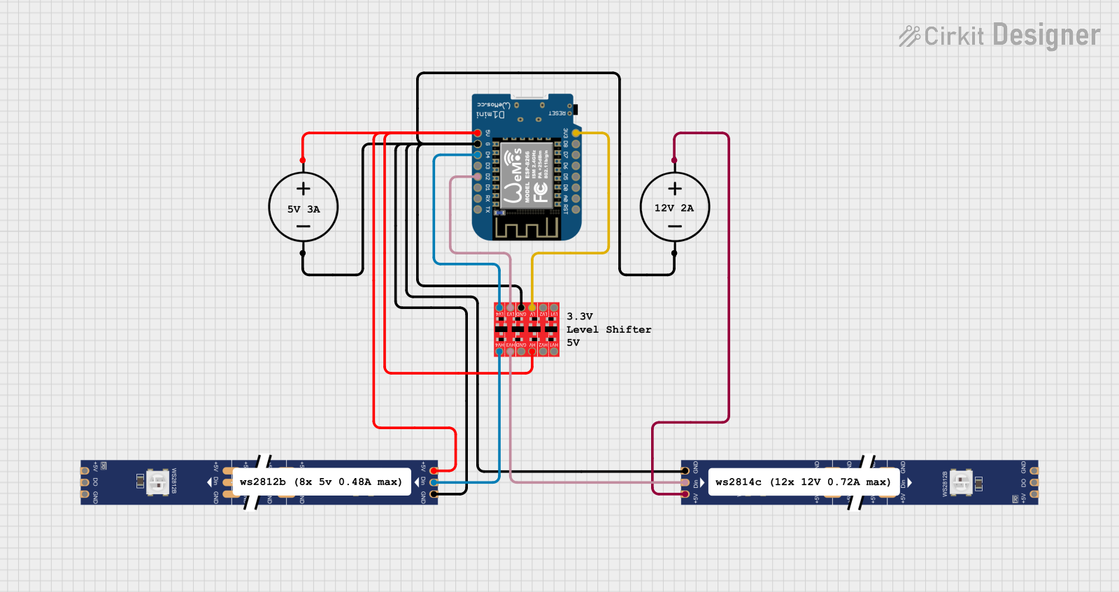
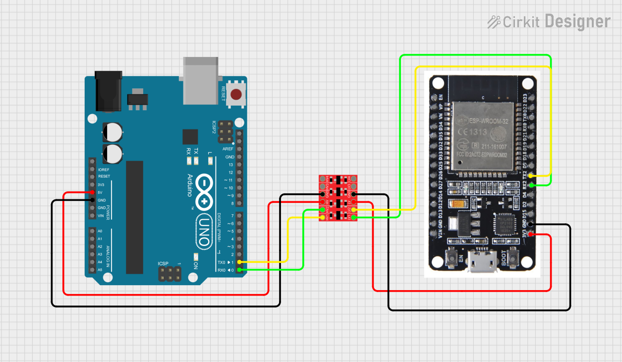
Explore Projects Built with Bi-Directional Logic Level Converter
Common Applications and Use Cases
- Interfacing 3.3V microcontrollers (e.g., ESP32, Raspberry Pi) with 5V devices (e.g., Arduino, sensors).
- Communication between I2C, SPI, or UART devices operating at different voltage levels.
- Safeguarding low-voltage devices from damage caused by higher voltage signals.
- Prototyping and development of mixed-voltage systems.
Technical Specifications
The Bi-Directional Logic Level Converter typically consists of four channels, allowing for the conversion of up to four signals simultaneously. Below are the key technical details:
Key Specifications
- Voltage Range (High Side): 3.3V to 5.5V
- Voltage Range (Low Side): 1.8V to 3.3V
- Maximum Data Rate: ~100 kHz (I2C) or higher for other protocols
- Channels: 4 independent bi-directional channels
- Dimensions: ~15mm x 15mm (varies by manufacturer)
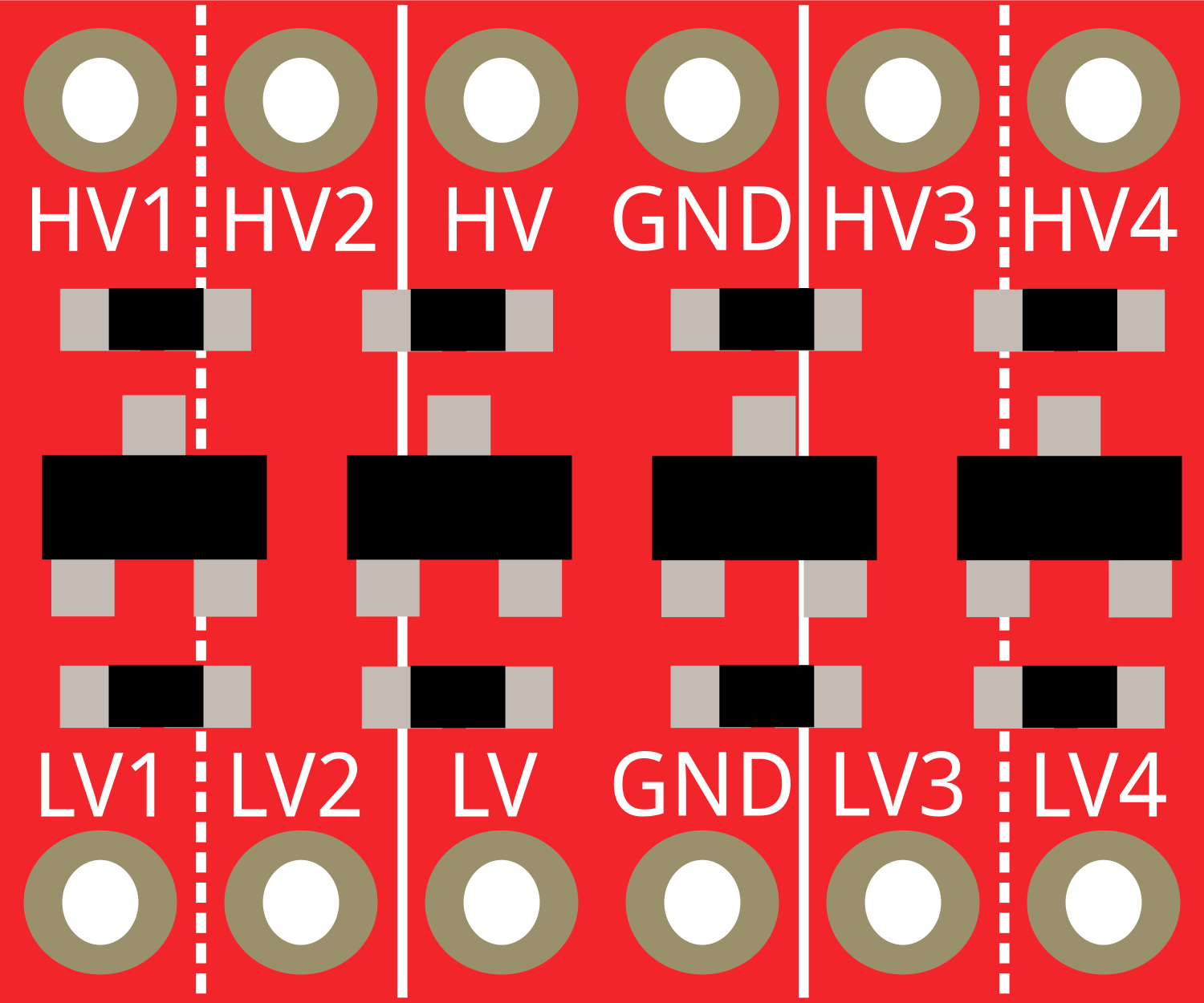
Pin Configuration and Descriptions
The Bi-Directional Logic Level Converter typically has the following pin layout:
| Pin Name | Description |
|---|---|
| HV | High voltage input (e.g., 5V). Powers the high-voltage side of the circuit. |
| LV | Low voltage input (e.g., 3.3V). Powers the low-voltage side of the circuit. |
| GND | Ground. Common ground for both high and low voltage sides. |
| TX1, RX1 | Channel 1 for bi-directional signal conversion. |
| TX2, RX2 | Channel 2 for bi-directional signal conversion. |
| TX3, RX3 | Channel 3 for bi-directional signal conversion. |
| TX4, RX4 | Channel 4 for bi-directional signal conversion. |
Note: Some modules may label the channels as
TXandRXor simply as1,2,3, and4. Always refer to the specific module's datasheet for exact pin labeling.
Usage Instructions
How to Use the Component in a Circuit
Power the Converter:
- Connect the HV pin to the high-voltage source (e.g., 5V).
- Connect the LV pin to the low-voltage source (e.g., 3.3V).
- Connect the GND pin to the common ground of both circuits.
Connect the Signal Lines:
- For each signal to be converted, connect the high-voltage side to the corresponding TX pin and the low-voltage side to the corresponding RX pin (or vice versa, depending on the direction of communication).
Verify Connections:
- Ensure that the voltage levels on the HV and LV pins match the operating voltages of the connected devices.
- Double-check the ground connection to avoid communication errors.
Important Considerations and Best Practices
- Voltage Compatibility: Ensure that the high and low voltage levels fall within the supported ranges of the converter.
- Data Rate Limitations: For high-speed communication protocols, verify that the converter can handle the required data rate.
- Pull-Up Resistors: Some I2C applications may require external pull-up resistors on the signal lines. Check your circuit requirements.
- Avoid Overloading: Do not exceed the maximum current rating of the converter.
Example: Connecting to an Arduino UNO
Below is an example of using the Bi-Directional Logic Level Converter to interface a 3.3V sensor with a 5V Arduino UNO via I2C.
Circuit Diagram
- HV: Connect to Arduino's 5V pin.
- LV: Connect to the sensor's 3.3V pin.
- GND: Connect to the common ground of the Arduino and the sensor.
- TX1/RX1: Connect to Arduino's SDA pin and the sensor's SDA pin.
- TX2/RX2: Connect to Arduino's SCL pin and the sensor's SCL pin.
Arduino Code Example
#include <Wire.h> // Include the Wire library for I2C communication

void setup() {
  Wire.begin(); // Initialize I2C communication
  Serial.begin(9600); // Start serial communication for debugging
  Serial.println("I2C Communication Initialized");
}

void loop() {
  Wire.beginTransmission(0x40); // Start communication with the sensor at address 0x40
  Wire.write(0x00); // Send a command or register address to the sensor
  Wire.endTransmission(); // End the transmission

  Wire.requestFrom(0x40, 2); // Request 2 bytes of data from the sensor
  if (Wire.available() == 2) { // Check if 2 bytes are available
    int data = Wire.read() << 8 | Wire.read(); // Read and combine the 2 bytes
    Serial.print("Sensor Data: ");
    Serial.println(data); // Print the sensor data to the Serial Monitor
  }

  delay(1000); // Wait for 1 second before the next reading
}
Note: Replace
0x40with the actual I2C address of your sensor.
Troubleshooting and FAQs
Common Issues and Solutions
No Communication Between Devices:
- Verify that the HV and LV pins are connected to the correct voltage sources.
- Ensure that the ground connection is shared between all devices.
Signal Distortion or Noise:
- Check for loose or poor-quality connections.
- Add pull-up resistors to the signal lines if required (e.g., for I2C).
Overheating of the Converter:
- Ensure that the current drawn by the connected devices does not exceed the converter's rating.
- Double-check the voltage levels on the HV and LV pins.
Data Transmission Errors:
- Verify the data rate of the communication protocol. If it's too high, consider reducing it.
- Check for proper termination of signal lines in long-distance communication.
FAQs
Q: Can I use the Bi-Directional Logic Level Converter for SPI communication?
A: Yes, the converter can be used for SPI communication. However, ensure that the data rate and voltage levels are within the supported range.
Q: Do I need external pull-up resistors for I2C?
A: Some modules include built-in pull-up resistors, but if your circuit requires stronger pull-ups, you may need to add external resistors (e.g., 4.7kΩ).
Q: Can I use this converter with 1.8V devices?
A: Yes, as long as the low-voltage side is powered at 1.8V and the high-voltage side is within the supported range (e.g., 3.3V to 5V).
Q: What happens if I reverse the HV and LV connections?
A: Reversing the connections can damage the converter or connected devices. Always double-check your wiring before powering the circuit.