Cirkit Designer Logo
Cirkit Designer
Your all-in-one circuit design IDE
Home / 
Component Documentation

How to Use Lilygo 7670e: Examples, Pinouts, and Specs

Image of Lilygo 7670e
Cirkit Designer LogoDesign with Lilygo 7670e in Cirkit Designer

Introduction

The Lilygo 7670e is a versatile development board that integrates the powerful ESP32-S2 wireless System on Chip (SoC) with the SIMCom SIM7670E module, providing LTE Cat 1 connectivity. This board is designed for Internet of Things (IoT) applications, offering a rich set of features including Wi-Fi, Bluetooth, and cellular connectivity. It is suitable for a wide range of applications such as smart home devices, industrial automation, and remote sensor networks.

Explore Projects Built with Lilygo 7670e

Use Cirkit Designer to design, explore, and prototype these projects online. Some projects support real-time simulation. Click "Open Project" to start designing instantly!
Lilygo 7670e-Based Smart Interface with LCD Display and Keypad
Image of Paower: A project utilizing Lilygo 7670e in a practical application
This circuit features a Lilygo 7670e microcontroller interfaced with a 16x2 I2C LCD for display, a 4X4 membrane matrix keypad for input, and an arcade button for additional control. It also includes a 4G antenna and a GPS antenna for communication and location tracking capabilities.
Cirkit Designer LogoOpen Project in Cirkit Designer
Cellular-Enabled IoT Device with Real-Time Clock and Power Management
Image of LRCM PHASE 2 BASIC: A project utilizing Lilygo 7670e in a practical application
This circuit features a LilyGo-SIM7000G module for cellular communication and GPS functionality, interfaced with an RTC DS3231 for real-time clock capabilities. It includes voltage sensing through two voltage sensor modules, and uses an 8-channel opto-coupler for isolating different parts of the circuit. Power management is handled by a buck converter connected to a DC power source and batteries, with a fuse for protection and a rocker switch for on/off control. Additionally, there's an LED for indication purposes.
Cirkit Designer LogoOpen Project in Cirkit Designer
Battery-Powered Emergency Alert System with NUCLEO-F072RB, SIM800L, and GPS NEO 6M
Image of women safety: A project utilizing Lilygo 7670e in a practical application
This circuit is an emergency alert system that uses a NUCLEO-F072RB microcontroller to send SMS alerts and make calls via a SIM800L GSM module, while obtaining location data from a GPS NEO 6M module. The system is powered by a Li-ion battery and includes a TP4056 module for battery charging and protection, with a rocker switch to control power to the microcontroller.
Cirkit Designer LogoOpen Project in Cirkit Designer
Cellular-Connected ESP32-CAM with Real-Time Clock and Isolated Control
Image of LRCM PHASE 2 PRO: A project utilizing Lilygo 7670e in a practical application
This circuit integrates a LilyGo-SIM7000G module with an RTC DS3231 for timekeeping, interfaced via I2C (SCL and SDA lines). An 8-Channel OPTO-COUPLER is used to isolate and interface external signals with the LilyGo-SIM7000G's GPIOs. Power is managed by a Buck converter, which steps down voltage from a DC Power Source to supply the ESP32-CAM and LilyGo-SIM7000G modules, as well as the OPTO-COUPLER.
Cirkit Designer LogoOpen Project in Cirkit Designer

Explore Projects Built with Lilygo 7670e

Use Cirkit Designer to design, explore, and prototype these projects online. Some projects support real-time simulation. Click "Open Project" to start designing instantly!
Image of Paower: A project utilizing Lilygo 7670e in a practical application
Lilygo 7670e-Based Smart Interface with LCD Display and Keypad
This circuit features a Lilygo 7670e microcontroller interfaced with a 16x2 I2C LCD for display, a 4X4 membrane matrix keypad for input, and an arcade button for additional control. It also includes a 4G antenna and a GPS antenna for communication and location tracking capabilities.
Cirkit Designer LogoOpen Project in Cirkit Designer
Image of LRCM PHASE 2 BASIC: A project utilizing Lilygo 7670e in a practical application
Cellular-Enabled IoT Device with Real-Time Clock and Power Management
This circuit features a LilyGo-SIM7000G module for cellular communication and GPS functionality, interfaced with an RTC DS3231 for real-time clock capabilities. It includes voltage sensing through two voltage sensor modules, and uses an 8-channel opto-coupler for isolating different parts of the circuit. Power management is handled by a buck converter connected to a DC power source and batteries, with a fuse for protection and a rocker switch for on/off control. Additionally, there's an LED for indication purposes.
Cirkit Designer LogoOpen Project in Cirkit Designer
Image of women safety: A project utilizing Lilygo 7670e in a practical application
Battery-Powered Emergency Alert System with NUCLEO-F072RB, SIM800L, and GPS NEO 6M
This circuit is an emergency alert system that uses a NUCLEO-F072RB microcontroller to send SMS alerts and make calls via a SIM800L GSM module, while obtaining location data from a GPS NEO 6M module. The system is powered by a Li-ion battery and includes a TP4056 module for battery charging and protection, with a rocker switch to control power to the microcontroller.
Cirkit Designer LogoOpen Project in Cirkit Designer
Image of LRCM PHASE 2 PRO: A project utilizing Lilygo 7670e in a practical application
Cellular-Connected ESP32-CAM with Real-Time Clock and Isolated Control
This circuit integrates a LilyGo-SIM7000G module with an RTC DS3231 for timekeeping, interfaced via I2C (SCL and SDA lines). An 8-Channel OPTO-COUPLER is used to isolate and interface external signals with the LilyGo-SIM7000G's GPIOs. Power is managed by a Buck converter, which steps down voltage from a DC Power Source to supply the ESP32-CAM and LilyGo-SIM7000G modules, as well as the OPTO-COUPLER.
Cirkit Designer LogoOpen Project in Cirkit Designer

Technical Specifications

General Features

  • Microcontroller: ESP32-S2
  • Cellular Module: SIMCom SIM7670E LTE Cat 1
  • Operating Voltage: 3.3V to 5V
  • Input Power: USB or battery
  • I/O Pins: Multiple GPIOs with various functions
  • Connectivity: Wi-Fi, Bluetooth, LTE Cat 1
  • USB: Built-in USB-to-serial for programming and power

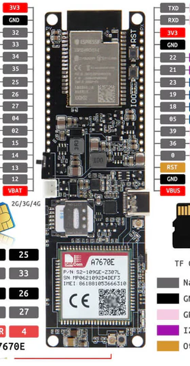
Pin Configuration and Descriptions

Pin Number Function Description
1 GND Ground
2 3V3 3.3V power supply
3 5V 5V power supply (USB or external source)
4 TX UART transmit for ESP32-S2
5 RX UART receive for ESP32-S2
6 GPIO General-purpose input/output
... ... ...
n ADC/DAC Analog-to-digital/digital-to-analog converter

Note: This is a simplified representation. Refer to the Lilygo 7670e datasheet for the complete pinout and alternate functions.

Usage Instructions

Integrating with a Circuit

  1. Power Supply: Ensure that the board is powered correctly using either a USB connection or an external battery. The input voltage should not exceed the specified limits.

  2. Programming: Connect the board to a computer using a USB cable. The built-in USB-to-serial converter allows for easy programming and communication with the ESP32-S2.

  3. Cellular Connectivity: Insert a nano-SIM card into the SIM card slot for LTE Cat 1 connectivity. Use the provided antenna connectors to attach the LTE antenna.

  4. I/O Connections: Utilize the GPIO pins for interfacing with sensors, actuators, and other peripherals. Ensure that the voltage levels are compatible with the ESP32-S2.

Best Practices

  • Always disconnect the power source before making or altering connections.
  • Use proper ESD protection when handling the board to prevent damage.
  • Ensure that the antenna is properly connected for optimal cellular reception.
  • Follow the ESP32-S2 datasheet guidelines for I/O pin current limits and voltage levels.

Troubleshooting and FAQs

Common Issues

  • Board not powering up: Check the USB cable and power source. Ensure the battery is charged if using external power.
  • No cellular connectivity: Verify that the SIM card is correctly inserted and activated. Check the antenna connections and placement.
  • Programming errors: Ensure that the correct drivers are installed and that the board is selected in the IDE.

Solutions and Tips

  • If the board does not power up, try a different USB cable or power source.
  • For cellular issues, confirm that the SIM card has an active data plan and the correct APN settings are used.
  • For programming issues, consult the ESP-IDF or Arduino documentation for setup instructions and troubleshooting steps.

FAQs

Q: Can the Lilygo 7670e be programmed using the Arduino IDE? A: Yes, the ESP32-S2 can be programmed using the Arduino IDE with the appropriate board package installed.

Q: What is the maximum baud rate for UART communication? A: The ESP32-S2 supports baud rates up to 5 Mbps, but the actual rate may be limited by the USB-to-serial converter.

Q: How do I update the firmware on the SIM7670E module? A: Firmware updates for the SIM7670E can be performed using the SIMCom provided tools and the UART interface.

Example Code for Arduino UNO

Below is a simple example code snippet for initializing the serial communication between the Lilygo 7670e and an Arduino UNO. This code is intended to demonstrate basic communication and is not a complete application.

#include <HardwareSerial.h>

HardwareSerial mySerial(1); // Use the appropriate hardware serial port

void setup() {
  // Start the built-in serial port, for communication with the computer
  Serial.begin(115200);
  while (!Serial) {
    ; // Wait for serial port to connect
  }

  // Start the hardware serial port, for communication with the Lilygo 7670e
  mySerial.begin(9600); // Adjust the baud rate as needed
}

void loop() {
  // Check if data is available on the built-in serial port
  if (Serial.available()) {
    // Read data from the computer and send it to the Lilygo 7670e
    mySerial.write(Serial.read());
  }

  // Check if data is available on the hardware serial port
  if (mySerial.available()) {
    // Read data from the Lilygo 7670e and send it to the computer
    Serial.write(mySerial.read());
  }
}

Note: This code is for demonstration purposes and may require modifications to work with specific applications or setups.

Remember to wrap the code comments as needed to limit line length to 80 characters.