
How to Use Digital Multimeter: Examples, Pinouts, and Specs
 Design with Digital Multimeter in Cirkit Designer
Introduction
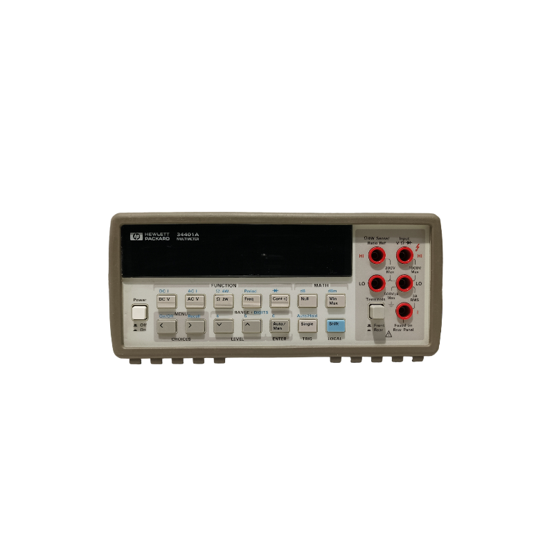
The Hewlett Packard (HP) 34401A Digital Multimeter is a versatile and precise electronic measuring instrument designed for laboratory and industrial applications. It combines multiple measurement functions into a single unit, allowing users to measure voltage, current, resistance, frequency, and more with high accuracy. The 34401A is widely recognized for its reliability, ease of use, and robust design, making it a popular choice among engineers, technicians, and hobbyists.
Explore Projects Built with Digital Multimeter
 Open Project in Cirkit Designer
 Open Project in Cirkit Designer
 Open Project in Cirkit Designer
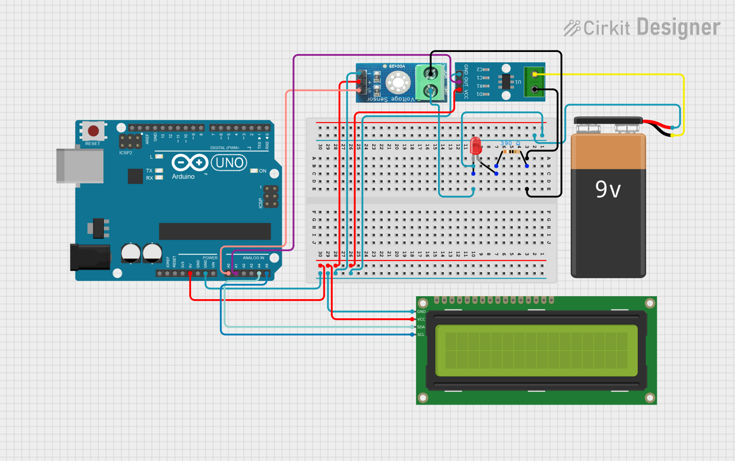 Open Project in Cirkit Designer
Explore Projects Built with Digital Multimeter
Open Project in Cirkit DesignerOpen Project in Cirkit DesignerOpen Project in Cirkit DesignerOpen Project in Cirkit DesignerCommon Applications and Use Cases
- Electronics Testing and Debugging: Measuring voltage, current, and resistance in circuits.
- Calibration and Quality Control: Ensuring components and systems meet design specifications.
- Educational Use: Teaching students about electrical measurements and circuit behavior.
- Industrial Maintenance: Diagnosing and troubleshooting electrical equipment.
Technical Specifications
The HP 34401A Digital Multimeter offers a range of features and specifications that make it suitable for a variety of applications.
Key Technical Details
| Specification | Value |
|---|---|
| Measurement Functions | DC Voltage, AC Voltage, DC Current, AC Current, Resistance, Frequency |
| DC Voltage Range | 100 mV to 1000 V |
| AC Voltage Range | 100 mV to 750 V |
| DC Current Range | 10 µA to 3 A |
| AC Current Range | 10 µA to 3 A |
| Resistance Range | 100 mΩ to 100 MΩ |
| Frequency Range | 3 Hz to 300 kHz |
| Display Resolution | 6½ digits |
| Accuracy | Up to 0.0035% for DC Voltage |
| Input Impedance | 10 MΩ (DC Voltage) |
| Power Supply | 100-240 V AC, 50/60 Hz |
| Dimensions | 88 mm x 213 mm x 348 mm |
| Weight | 3.6 kg |
Pin Configuration and Descriptions
The HP 34401A does not have a traditional pin configuration like ICs or microcontrollers. Instead, it features input terminals for connecting test leads. Below is a description of the input terminals:
| Terminal | Description |
|---|---|
| V/Ω Input | Used for measuring voltage (AC/DC) and resistance. |
| COM (Common) | Common ground terminal for all measurements. |
| I Input | Used for measuring current (AC/DC) up to 3 A. |
| Sense Terminals | For 4-wire resistance measurements to improve accuracy by eliminating lead resistance. |
Usage Instructions
The HP 34401A Digital Multimeter is straightforward to use, but following proper procedures ensures accurate and safe measurements.
How to Use the Component in a Circuit
- Power On: Connect the multimeter to a power source and turn it on using the power button.
- Select Measurement Mode:
- Use the function buttons to select the desired measurement mode (e.g., DC Voltage, Resistance).
- Connect Test Leads:
- Insert the red test lead into the appropriate input terminal (e.g., V/Ω for voltage or resistance).
- Insert the black test lead into the COM terminal.
- Perform Measurement:
- For voltage or resistance, connect the test leads across the component or circuit.
- For current, connect the multimeter in series with the circuit.
- Read the Display: The measurement result will appear on the 6½-digit display.
Important Considerations and Best Practices
- Input Limits: Do not exceed the maximum input ratings for voltage, current, or resistance to avoid damage.
- 4-Wire Resistance Measurement: Use the sense terminals for high-accuracy resistance measurements.
- Warm-Up Time: Allow the multimeter to warm up for 30 minutes for the most accurate readings.
- Calibration: Periodically calibrate the multimeter to maintain accuracy.
- Safety: Always ensure the multimeter is set to the correct mode before connecting it to a circuit.
Example: Measuring Voltage with Arduino UNO
The HP 34401A can be used to measure the voltage output of an Arduino UNO. Below is an example setup:
- Connect the Arduino UNO's 5V pin to the V/Ω input terminal of the multimeter.
- Connect the Arduino UNO's GND pin to the COM terminal of the multimeter.
- Set the multimeter to DC Voltage mode.
- Read the voltage output on the multimeter display.
// Arduino code to output a fixed voltage on a PWM pin
void setup() {
  pinMode(9, OUTPUT); // Set pin 9 as an output
  analogWrite(9, 128); // Output a PWM signal with 50% duty cycle
}

void loop() {
  // No additional code needed for this example
}
Troubleshooting and FAQs
Common Issues Users Might Face
No Display or Power:
- Cause: The multimeter is not connected to a power source or the fuse is blown.
- Solution: Check the power connection and replace the fuse if necessary.
Inaccurate Measurements:
- Cause: The multimeter is not calibrated or the test leads are damaged.
- Solution: Perform calibration and inspect/replace test leads.
Overload Indication:
- Cause: The input exceeds the maximum range of the selected mode.
- Solution: Switch to a higher range or reduce the input signal.
No Current Measurement:
- Cause: The current input fuse is blown.
- Solution: Replace the current input fuse.
Solutions and Tips for Troubleshooting
- Check Connections: Ensure test leads are securely connected to the terminals.
- Verify Settings: Double-check that the multimeter is in the correct mode for the measurement.
- Inspect Test Leads: Look for frayed or broken wires in the test leads.
- Consult the Manual: Refer to the HP 34401A user manual for detailed troubleshooting steps.
By following this documentation, users can effectively utilize the HP 34401A Digital Multimeter for a wide range of measurement tasks.