Cirkit Designer Logo
Cirkit Designer
Your all-in-one circuit design IDE
Home / 
Component Documentation

How to Use XT30 Connector: Examples, Pinouts, and Specs

Image of XT30 Connector
Cirkit Designer LogoDesign with XT30 Connector in Cirkit Designer

Introduction

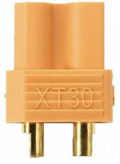
The XT30 connector is a compact, lightweight, and durable electrical connector designed for high-current applications. It is widely used in remote-controlled (RC) vehicles, drones, and other electronic systems to connect batteries to electronic speed controllers (ESCs) or other power-hungry components. Its small size and reliable connection make it ideal for applications where space and weight are critical factors.

Explore Projects Built with XT30 Connector

Use Cirkit Designer to design, explore, and prototype these projects online. Some projects support real-time simulation. Click "Open Project" to start designing instantly!
FTDI to UART Adapter with J26 Connector
Image of J26 CLOSEUP: A project utilizing XT30 Connector in a practical application
This circuit connects an FTDI USB-to-serial converter to a standard serial interface via a J26 connector. It facilitates serial communication by linking the ground, transmit, receive, data terminal ready, and request to send signals between the FTDI chip and the J26 connector.
Cirkit Designer LogoOpen Project in Cirkit Designer
Satellite-Based Timing and Navigation System with SDR and Atomic Clock Synchronization
Image of GPS 시스템 측정 구성도_Confirm: A project utilizing XT30 Connector in a practical application
This circuit appears to be a complex system involving power supply management, GPS and timing synchronization, and data communication. It includes a SI-TEX G1 Satellite Compass for GPS data, an XHTF1021 Atomic Rubidium Clock for precise timing, and Ettus USRP B200 units for software-defined radio communication. Power is supplied through various SMPS units and distributed via terminal blocks and DC jacks. Data communication is facilitated by Beelink MINI S12 N95 computers, RS232 splitters, and a 1000BASE-T Media Converter for network connectivity. RF Directional Couplers are used to interface antennas with the USRP units, and the entire system is likely contained within cases for protection and organization.
Cirkit Designer LogoOpen Project in Cirkit Designer
ESP32-CAM Module with USB to TTL Communication
Image of S: A project utilizing XT30 Connector in a practical application
This circuit connects an ESP32-CAM module to a USB to TTL module for serial communication and power supply. The ESP32-CAM's transmit (VOT) and receive (VOR) pins are connected to the USB to TTL's RXD and TXD pins respectively, enabling serial data exchange between the ESP32-CAM and a connected computer. Power (3V3 and 5V) and ground (GND) connections are also established between the two modules, ensuring the ESP32-CAM is powered and can communicate over USB.
Cirkit Designer LogoOpen Project in Cirkit Designer
Satellite Compass and Network-Integrated GPS Data Processing System
Image of GPS 시스템 측정 구성도_241016: A project utilizing XT30 Connector in a practical application
This circuit comprises a satellite compass, a mini PC, two GPS antennas, power supplies, a network switch, media converters, and an atomic rubidium clock. The satellite compass is powered by a triple output DC power supply and interfaces with an RS232 splitter for 1PPS signals. The mini PCs are connected to the USRP B200 devices via USB for data and power, and to media converters via Ethernet, which in turn connect to a network switch using fiber optic links. The antennas are connected to the USRP B200s through RF directional couplers, and the atomic clock provides a 1PPS input to the RS232 splitter.
Cirkit Designer LogoOpen Project in Cirkit Designer

Explore Projects Built with XT30 Connector

Use Cirkit Designer to design, explore, and prototype these projects online. Some projects support real-time simulation. Click "Open Project" to start designing instantly!
Image of J26 CLOSEUP: A project utilizing XT30 Connector in a practical application
FTDI to UART Adapter with J26 Connector
This circuit connects an FTDI USB-to-serial converter to a standard serial interface via a J26 connector. It facilitates serial communication by linking the ground, transmit, receive, data terminal ready, and request to send signals between the FTDI chip and the J26 connector.
Cirkit Designer LogoOpen Project in Cirkit Designer
Image of GPS 시스템 측정 구성도_Confirm: A project utilizing XT30 Connector in a practical application
Satellite-Based Timing and Navigation System with SDR and Atomic Clock Synchronization
This circuit appears to be a complex system involving power supply management, GPS and timing synchronization, and data communication. It includes a SI-TEX G1 Satellite Compass for GPS data, an XHTF1021 Atomic Rubidium Clock for precise timing, and Ettus USRP B200 units for software-defined radio communication. Power is supplied through various SMPS units and distributed via terminal blocks and DC jacks. Data communication is facilitated by Beelink MINI S12 N95 computers, RS232 splitters, and a 1000BASE-T Media Converter for network connectivity. RF Directional Couplers are used to interface antennas with the USRP units, and the entire system is likely contained within cases for protection and organization.
Cirkit Designer LogoOpen Project in Cirkit Designer
Image of S: A project utilizing XT30 Connector in a practical application
ESP32-CAM Module with USB to TTL Communication
This circuit connects an ESP32-CAM module to a USB to TTL module for serial communication and power supply. The ESP32-CAM's transmit (VOT) and receive (VOR) pins are connected to the USB to TTL's RXD and TXD pins respectively, enabling serial data exchange between the ESP32-CAM and a connected computer. Power (3V3 and 5V) and ground (GND) connections are also established between the two modules, ensuring the ESP32-CAM is powered and can communicate over USB.
Cirkit Designer LogoOpen Project in Cirkit Designer
Image of GPS 시스템 측정 구성도_241016: A project utilizing XT30 Connector in a practical application
Satellite Compass and Network-Integrated GPS Data Processing System
This circuit comprises a satellite compass, a mini PC, two GPS antennas, power supplies, a network switch, media converters, and an atomic rubidium clock. The satellite compass is powered by a triple output DC power supply and interfaces with an RS232 splitter for 1PPS signals. The mini PCs are connected to the USRP B200 devices via USB for data and power, and to media converters via Ethernet, which in turn connect to a network switch using fiber optic links. The antennas are connected to the USRP B200s through RF directional couplers, and the atomic clock provides a 1PPS input to the RS232 splitter.
Cirkit Designer LogoOpen Project in Cirkit Designer

Common Applications

  • RC vehicles (cars, boats, planes, etc.)
  • Drones and quadcopters
  • Battery packs for portable electronics
  • Robotics and small-scale industrial equipment
  • DIY electronics projects requiring high-current connections

Technical Specifications

The XT30 connector is designed to handle high currents while maintaining a secure and low-resistance connection. Below are its key technical details:

Parameter Specification
Rated Current 30A continuous
Peak Current 60A (short bursts)
Voltage Rating Up to 500V DC
Contact Material Gold-plated copper
Insulation Material Heat-resistant nylon (up to 260°C)
Connector Type Male and female pair
Wire Gauge Support 16 AWG to 20 AWG
Dimensions (per side) 13.5mm x 8mm x 4.5mm
Weight (per pair) ~2.3 grams

Pin Configuration and Descriptions

The XT30 connector consists of two pins: one for positive voltage and one for ground. The pins are polarized to prevent reverse polarity connections.

Pin Description Notes
1 Positive (+) Terminal Connects to the positive terminal of the battery or power source.
2 Ground (-) Terminal Connects to the ground terminal of the battery or power source.

Usage Instructions

How to Use the XT30 Connector in a Circuit

  1. Prepare the Wires: Strip the insulation from the ends of the wires you intend to connect to the XT30 connector. Ensure the exposed wire length matches the connector's solder cups.
  2. Solder the Wires:
    • Heat the soldering iron to 350°C–400°C.
    • Tin the exposed wire ends and the solder cups of the XT30 connector with a small amount of solder.
    • Insert the tinned wire into the corresponding solder cup (positive or ground) and apply heat until the solder flows and creates a secure connection.
  3. Insulate the Connection: Use heat shrink tubing to cover the soldered joints for added insulation and strain relief.
  4. Connect the Male and Female Parts: Plug the male and female connectors together, ensuring the polarity matches (positive to positive, ground to ground).

Important Considerations and Best Practices

  • Polarity: Always double-check the polarity before connecting the XT30 to avoid damaging your components.
  • Wire Gauge: Use wires within the supported range (16–20 AWG) to ensure proper current handling and minimize resistance.
  • Soldering: Avoid overheating the connector during soldering, as excessive heat can deform the nylon housing.
  • Secure Fit: Ensure the male and female connectors are fully mated to prevent loose connections during operation.
  • Heat Management: For high-current applications, monitor the connector's temperature to avoid overheating.

Example: Connecting an XT30 to an Arduino UNO

While the XT30 is not directly connected to an Arduino UNO, it can be used to supply power to the Arduino via a voltage regulator or battery pack. Below is an example of using an XT30 connector with a 7.4V LiPo battery to power an Arduino UNO:

// Example: Powering an Arduino UNO with an XT30-connected LiPo battery
// Ensure the LiPo battery voltage is regulated to 5V before connecting to the Arduino.

void setup() {
  // Initialize the Arduino (no specific setup needed for power input)
}

void loop() {
  // Your main code here
  // The Arduino is powered via the XT30-connected battery
}

Note: Use a voltage regulator (e.g., LM7805) to step down the battery voltage to 5V if the battery voltage exceeds the Arduino's input voltage range.

Troubleshooting and FAQs

Common Issues

  1. Loose Connection:

    • Cause: Incomplete mating of the male and female connectors.
    • Solution: Ensure the connectors are fully inserted and locked in place.
  2. Overheating:

    • Cause: Exceeding the rated current or poor soldering.
    • Solution: Verify the current draw of your circuit and ensure proper soldering techniques.
  3. Reverse Polarity:

    • Cause: Incorrect wiring of the positive and ground terminals.
    • Solution: Double-check the polarity before connecting the XT30 to your circuit.
  4. Melted Housing:

    • Cause: Excessive heat during soldering.
    • Solution: Use a temperature-controlled soldering iron and limit soldering time to a few seconds per joint.

FAQs

Q: Can the XT30 connector handle currents above 30A?
A: The XT30 is rated for 30A continuous current. It can handle short bursts of up to 60A, but prolonged use above 30A may cause overheating and damage.

Q: Is the XT30 connector waterproof?
A: No, the XT30 connector is not waterproof. For outdoor or wet environments, consider using additional waterproofing measures, such as heat shrink tubing with adhesive.

Q: Can I use the XT30 connector with thicker wires (e.g., 14 AWG)?
A: The XT30 is designed for 16–20 AWG wires. Using thicker wires may require modification, but this is not recommended as it could compromise the connection.

Q: How do I disconnect the XT30 connector?
A: Hold the male and female connectors firmly and pull them apart. Avoid pulling on the wires to prevent damage.

By following this documentation, you can effectively use the XT30 connector in your projects and ensure reliable, high-current connections.