How to Use Alternative Current (AC) - Large: Examples, Pinouts, and Specs

Introduction
Alternative Current (AC) is a type of electrical current in which the flow of electric charge periodically reverses direction. This is in contrast to Direct Current (DC), where the flow of electric charge is only in one direction. AC is typically used in large-scale power distribution systems due to its efficiency in transmitting power over long distances. Common applications include household electrical outlets, industrial machinery, and large-scale power grids.
Explore Projects Built with Alternative Current (AC) - Large
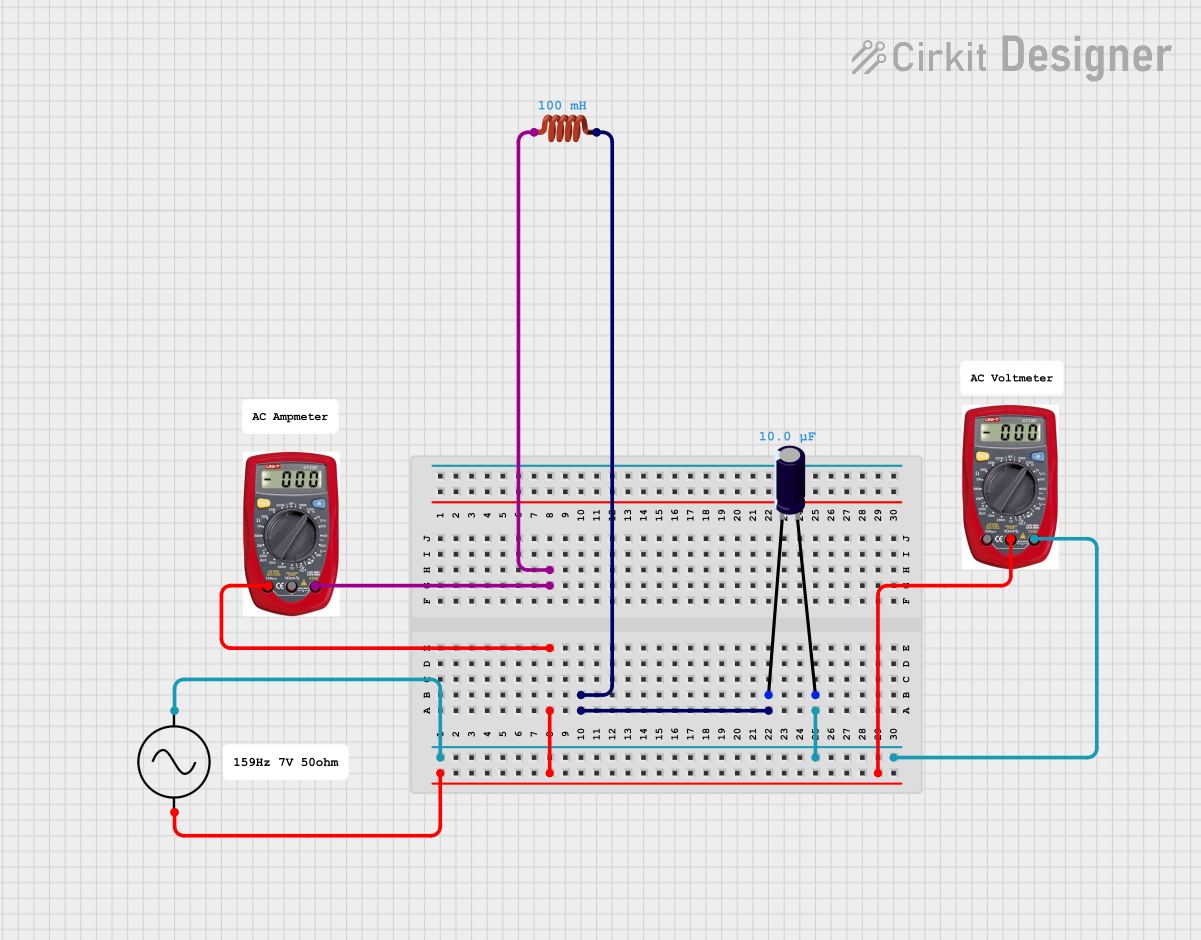
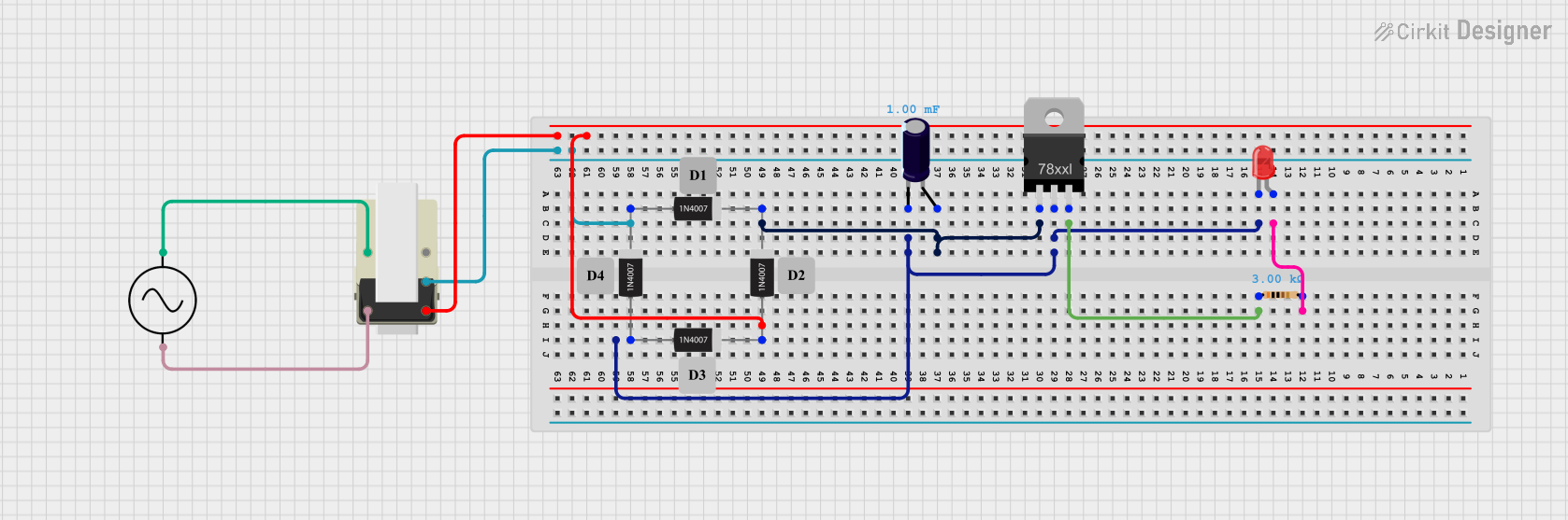

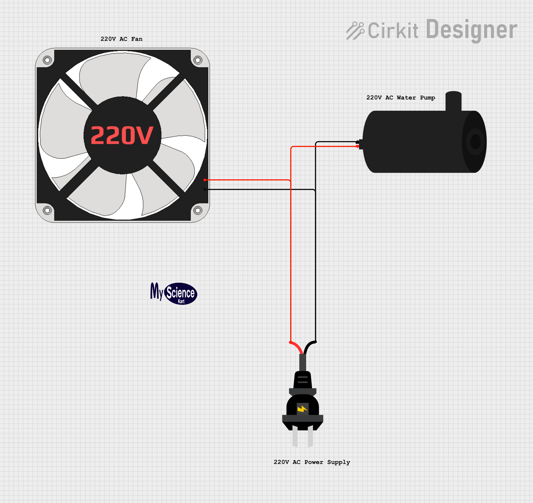
Explore Projects Built with Alternative Current (AC) - Large
Technical Specifications
Key Technical Details
| Parameter | Value |
|---|---|
| Voltage Range | 110V - 240V |
| Frequency | 50Hz or 60Hz |
| Power Rating | Up to 10,000W (10kW) |
| Phase Configuration | Single-phase or Three-phase |
| Current Rating | Up to 100A |
Pin Configuration and Descriptions
For a typical AC plug:
| Pin Number | Pin Name | Description |
|---|---|---|
| 1 | Live (L) | Carries the current to the load |
| 2 | Neutral (N) | Returns the current from the load |
| 3 | Ground (G) | Safety ground to prevent electric shock |
Usage Instructions
How to Use the Component in a Circuit
- Safety First: Always ensure that the power is turned off before working with AC circuits to avoid electric shock.
- Connection: Connect the Live (L) wire to the load's input terminal, the Neutral (N) wire to the load's return terminal, and the Ground (G) wire to the load's ground terminal.
- Testing: Use a multimeter to verify the connections and ensure there are no short circuits.
- Power On: Once all connections are verified, turn on the power supply.
Important Considerations and Best Practices
- Insulation: Ensure all wires are properly insulated to prevent short circuits and electric shocks.
- Grounding: Always connect the ground wire to prevent electric shock and ensure safety.
- Load Rating: Do not exceed the power rating of the component to avoid overheating and potential fire hazards.
- Regular Maintenance: Periodically check the connections and insulation for wear and tear.
Troubleshooting and FAQs
Common Issues Users Might Face
No Power to Load:
- Solution: Check if the power supply is turned on and verify all connections with a multimeter.
Circuit Breaker Trips:
- Solution: Ensure the load does not exceed the current rating. Check for short circuits or faulty components.
Electric Shock:
- Solution: Immediately turn off the power supply. Verify that all connections are properly insulated and the ground wire is connected.
FAQs
Can I use AC with an Arduino UNO?
- Answer: Directly connecting AC to an Arduino UNO is not recommended. Use a relay module or an optocoupler to interface AC with the Arduino.
What is the difference between single-phase and three-phase AC?
- Answer: Single-phase AC uses one alternating voltage, while three-phase AC uses three alternating voltages, each 120 degrees out of phase with the others. Three-phase AC is more efficient for large power loads.
How do I measure AC voltage and current?
- Answer: Use a multimeter set to the appropriate AC voltage or current range. Ensure the multimeter probes are properly connected to the circuit.
Example Code for Arduino UNO
If you need to control an AC load using an Arduino UNO, you can use a relay module. Below is an example code to turn an AC load on and off using a relay module connected to pin 7 of the Arduino UNO.
// Define the relay pin
const int relayPin = 7;

void setup() {
  // Initialize the relay pin as an output
  pinMode(relayPin, OUTPUT);
  // Start with the relay off
  digitalWrite(relayPin, LOW);
}

void loop() {
  // Turn the relay on (AC load on)
  digitalWrite(relayPin, HIGH);
  delay(1000); // Wait for 1 second

  // Turn the relay off (AC load off)
  digitalWrite(relayPin, LOW);
  delay(1000); // Wait for 1 second
}
This code will toggle the AC load on and off every second. Ensure that the relay module is rated for the AC voltage and current you are using.
This documentation provides a comprehensive overview of the Alternative Current (AC) - Large component, including its technical specifications, usage instructions, and troubleshooting tips. Whether you are a beginner or an experienced user, this guide will help you safely and effectively use AC in your projects.