Cirkit Designer Logo
Cirkit Designer
Your all-in-one circuit design IDE
Home / 
Component Documentation

How to Use ESP32-WROOM-32D: Examples, Pinouts, and Specs

Image of ESP32-WROOM-32D
Cirkit Designer LogoDesign with ESP32-WROOM-32D in Cirkit Designer

Introduction

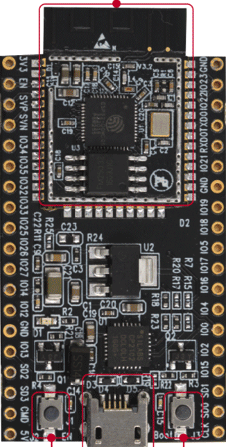
The ESP32-WROOM-32D is a high-performance Wi-Fi and Bluetooth microcontroller module manufactured by Espressif Systems. It features dual-core processing, integrated RF components, and a rich set of peripherals, making it an ideal choice for IoT applications, smart devices, and embedded systems. With its compact design and robust capabilities, the ESP32-WROOM-32D is widely used in projects requiring wireless connectivity and efficient processing.

Explore Projects Built with ESP32-WROOM-32D

Use Cirkit Designer to design, explore, and prototype these projects online. Some projects support real-time simulation. Click "Open Project" to start designing instantly!
ESP32-Based GPS Tracker with SD Card Logging and Barometric Sensor
Image of gps projekt circuit: A project utilizing ESP32-WROOM-32D in a practical application
This circuit features an ESP32 Wroom Dev Kit as the main microcontroller, interfaced with an MPL3115A2 sensor for pressure and temperature readings, and a Neo 6M GPS module for location tracking. The ESP32 is also connected to an SD card reader for data logging purposes. A voltage regulator is used to step down the USB power supply to 3.3V, which powers the ESP32, the sensor, and the SD card reader.
Cirkit Designer LogoOpen Project in Cirkit Designer
ESP32-Based Multi-Sensor Health Monitoring System with Bluetooth Connectivity
Image of circuit diagram: A project utilizing ESP32-WROOM-32D in a practical application
This circuit features an ESP32-WROOM-32UE microcontroller as the central processing unit, interfacing with a variety of sensors and modules. It includes a MAX30100 pulse oximeter and heart-rate sensor, an MLX90614 infrared thermometer, an HC-05 Bluetooth module for wireless communication, and a Neo 6M GPS module for location tracking. All components are powered by a common voltage supply and are connected to specific GPIO pins on the ESP32 for data exchange, with the sensors using I2C communication and the modules using UART.
Cirkit Designer LogoOpen Project in Cirkit Designer
ESP32-Based Environmental and Magnetic Field Monitoring System with OLED Display
Image of nam: A project utilizing ESP32-WROOM-32D in a practical application
This circuit features an ESP32 microcontroller connected to a DHT11 temperature and humidity sensor, two Hall effect sensors for detecting magnetic fields, an OLED display for output, and a buzzer for audible alerts. The ESP32 reads temperature and humidity data from the DHT11 sensor and magnetic field data from the Hall sensors, displaying the information on the OLED screen and potentially triggering the buzzer based on certain conditions. The ESP32 manages power distribution to the sensors and the display, and communicates with the OLED via I2C (SCL and SDA lines connected to pins 22 and 21 respectively).
Cirkit Designer LogoOpen Project in Cirkit Designer
ESP32-Based Infrared Proximity Sensing System
Image of ir sensor: A project utilizing ESP32-WROOM-32D in a practical application
This circuit features an ESP32 Wroom microcontroller connected to an Infrared Proximity Sensor. The ESP32's GPIO33 is interfaced with the sensor's output, allowing the microcontroller to read proximity data. The sensor is powered by the ESP32's 5V output, and both devices share a common ground.
Cirkit Designer LogoOpen Project in Cirkit Designer

Explore Projects Built with ESP32-WROOM-32D

Use Cirkit Designer to design, explore, and prototype these projects online. Some projects support real-time simulation. Click "Open Project" to start designing instantly!
Image of gps projekt circuit: A project utilizing ESP32-WROOM-32D in a practical application
ESP32-Based GPS Tracker with SD Card Logging and Barometric Sensor
This circuit features an ESP32 Wroom Dev Kit as the main microcontroller, interfaced with an MPL3115A2 sensor for pressure and temperature readings, and a Neo 6M GPS module for location tracking. The ESP32 is also connected to an SD card reader for data logging purposes. A voltage regulator is used to step down the USB power supply to 3.3V, which powers the ESP32, the sensor, and the SD card reader.
Cirkit Designer LogoOpen Project in Cirkit Designer
Image of circuit diagram: A project utilizing ESP32-WROOM-32D in a practical application
ESP32-Based Multi-Sensor Health Monitoring System with Bluetooth Connectivity
This circuit features an ESP32-WROOM-32UE microcontroller as the central processing unit, interfacing with a variety of sensors and modules. It includes a MAX30100 pulse oximeter and heart-rate sensor, an MLX90614 infrared thermometer, an HC-05 Bluetooth module for wireless communication, and a Neo 6M GPS module for location tracking. All components are powered by a common voltage supply and are connected to specific GPIO pins on the ESP32 for data exchange, with the sensors using I2C communication and the modules using UART.
Cirkit Designer LogoOpen Project in Cirkit Designer
Image of nam: A project utilizing ESP32-WROOM-32D in a practical application
ESP32-Based Environmental and Magnetic Field Monitoring System with OLED Display
This circuit features an ESP32 microcontroller connected to a DHT11 temperature and humidity sensor, two Hall effect sensors for detecting magnetic fields, an OLED display for output, and a buzzer for audible alerts. The ESP32 reads temperature and humidity data from the DHT11 sensor and magnetic field data from the Hall sensors, displaying the information on the OLED screen and potentially triggering the buzzer based on certain conditions. The ESP32 manages power distribution to the sensors and the display, and communicates with the OLED via I2C (SCL and SDA lines connected to pins 22 and 21 respectively).
Cirkit Designer LogoOpen Project in Cirkit Designer
Image of ir sensor: A project utilizing ESP32-WROOM-32D in a practical application
ESP32-Based Infrared Proximity Sensing System
This circuit features an ESP32 Wroom microcontroller connected to an Infrared Proximity Sensor. The ESP32's GPIO33 is interfaced with the sensor's output, allowing the microcontroller to read proximity data. The sensor is powered by the ESP32's 5V output, and both devices share a common ground.
Cirkit Designer LogoOpen Project in Cirkit Designer

Common Applications and Use Cases

  • Internet of Things (IoT) devices
  • Smart home automation systems
  • Wearable electronics
  • Wireless sensor networks
  • Industrial automation
  • Robotics and drones
  • Prototyping and development of connected devices

Technical Specifications

The ESP32-WROOM-32D module is built around the ESP32-D0WD chip, offering a balance of performance, power efficiency, and connectivity.

Key Technical Details

Parameter Specification
Manufacturer Espressif Systems
Part Number ESP32D
Wireless Connectivity Wi-Fi 802.11 b/g/n, Bluetooth v4.2 BR/EDR and BLE
Processor Dual-core Xtensa® 32-bit LX6
Clock Speed Up to 240 MHz
Flash Memory 4 MB (external SPI flash)
SRAM 520 KB
Operating Voltage 3.0V to 3.6V
GPIO Pins 34
ADC Channels 18
DAC Channels 2
Communication Interfaces UART, SPI, I2C, I2S, CAN, PWM
Operating Temperature -40°C to +85°C
Dimensions 18 mm x 25.5 mm x 3.1 mm

Pin Configuration and Descriptions

The ESP32-WROOM-32D module has 38 pins. Below is a table summarizing the key pin functions:

Pin Number Name Function Description
1 EN Enable pin. Active high to enable the module.
2 IO0 GPIO0, used for boot mode selection.
3 IO1 (TX0) GPIO1, UART0 TXD (default).
4 IO3 (RX0) GPIO3, UART0 RXD (default).
5 IO4 GPIO4, general-purpose I/O.
6 IO5 GPIO5, general-purpose I/O.
7 GND Ground.
8 3V3 3.3V power supply input.
9 IO12 GPIO12, supports ADC2 and touch input.
10 IO13 GPIO13, supports ADC2 and touch input.
... ... ...
38 IO39 GPIO39, ADC1 channel 3.

Note: For the full pinout and detailed descriptions, refer to the official datasheet.

Usage Instructions

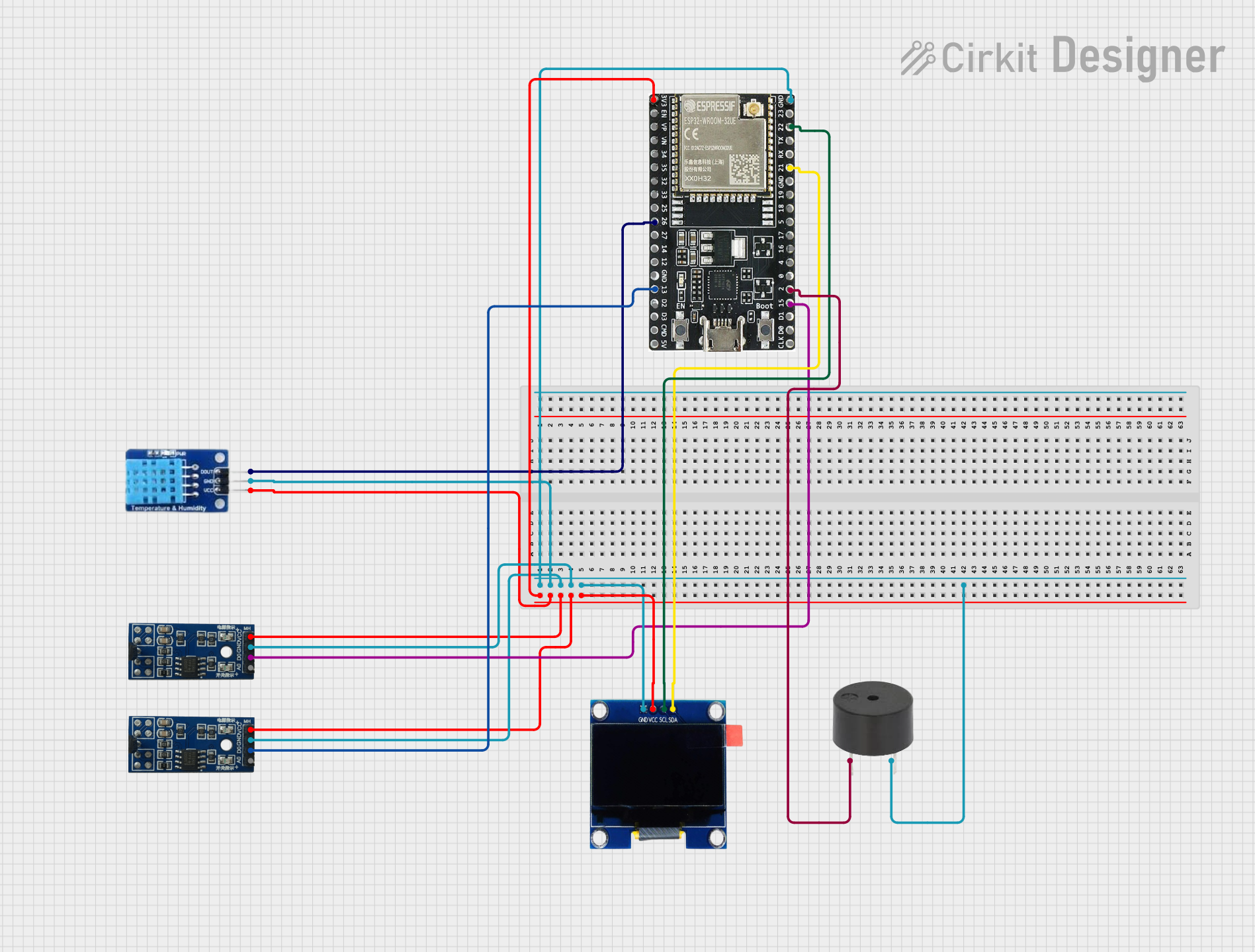
How to Use the ESP32-WROOM-32D in a Circuit

  1. Power Supply: Provide a stable 3.3V power supply to the module. Ensure the current supply is sufficient for Wi-Fi and Bluetooth operations (at least 500 mA).
  2. Boot Mode: Connect GPIO0 to GND during power-up to enter bootloader mode for programming.
  3. Connections:
    • Use UART pins (TX0 and RX0) for serial communication and programming.
    • Connect GPIO pins to peripherals as needed (e.g., sensors, actuators).
  4. Antenna: Ensure the onboard PCB antenna is not obstructed for optimal wireless performance.

Important Considerations and Best Practices

  • Voltage Levels: All GPIO pins are 3.3V logic level. Avoid applying 5V directly to any pin.
  • Decoupling Capacitors: Place decoupling capacitors near the power pins to reduce noise.
  • Programming: Use the Espressif ESP-IDF or Arduino IDE for development. Install the necessary drivers and tools for your operating system.
  • Heat Management: Ensure proper ventilation or heat dissipation if the module operates under high loads.

Example Code for Arduino IDE

Below is an example of how to connect the ESP32-WROOM-32D to an Arduino IDE and blink an LED:

// Example: Blink an LED using ESP32-WROOM-32D
// Connect an LED to GPIO2 with a 220-ohm resistor.

#define LED_PIN 2  // GPIO2 is connected to the LED

void setup() {
  pinMode(LED_PIN, OUTPUT);  // Set GPIO2 as an output pin
}

void loop() {
  digitalWrite(LED_PIN, HIGH);  // Turn the LED on
  delay(1000);                  // Wait for 1 second
  digitalWrite(LED_PIN, LOW);   // Turn the LED off
  delay(1000);                  // Wait for 1 second
}

Tip: Ensure the correct board and COM port are selected in the Arduino IDE before uploading the code.

Troubleshooting and FAQs

Common Issues and Solutions

  1. Module Not Responding:

    • Ensure the EN pin is pulled high.
    • Verify the power supply voltage is within the 3.0V to 3.6V range.
    • Check the connections to the UART interface.
  2. Wi-Fi Connection Fails:

    • Verify the SSID and password in your code.
    • Ensure the antenna is unobstructed and within range of the Wi-Fi router.
  3. GPIO Pins Not Working:

    • Confirm the pin mode is correctly set in the code.
    • Check for conflicting pin assignments in your circuit.
  4. Programming Errors:

    • Ensure GPIO0 is connected to GND during programming.
    • Verify the correct COM port and baud rate (default: 115200).

FAQs

Q: Can the ESP32-WROOM-32D operate on 5V?
A: No, the module operates on 3.3V. Applying 5V to any pin may damage the module.

Q: How do I reset the module?
A: Pull the EN pin low momentarily to reset the module.

Q: Can I use the ESP32-WROOM-32D with a 5V logic microcontroller?
A: Use a level shifter to safely interface 5V logic with the 3.3V GPIO pins of the ESP32.

Q: What is the maximum Wi-Fi range?
A: The range depends on environmental factors but typically extends up to 100 meters in open space.

For additional support, refer to the official Espressif documentation or community forums.