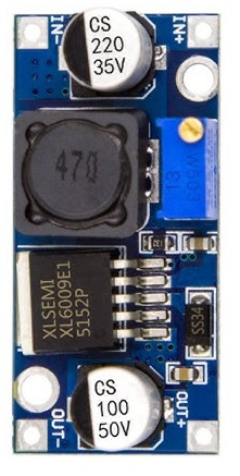
How to Use STEP-UP CONVERTER: Examples, Pinouts, and Specs
Introduction
A step-up converter, also known as a boost converter, is a type of DC-DC converter that increases the input voltage to a higher output voltage. This component is widely used in applications where a higher voltage is required than what is available from the power source. It is commonly employed in battery-powered devices, renewable energy systems, and LED drivers.
Explore Projects Built with STEP-UP CONVERTER


Explore Projects Built with STEP-UP CONVERTER
Common Applications and Use Cases
- Powering devices requiring higher voltage from a low-voltage source (e.g., 5V to 12V).
- Boosting voltage in solar power systems.
- Driving high-power LEDs.
- Battery-powered systems where efficient voltage conversion is critical.
Technical Specifications
Below are the key technical details for the DC-DC Step-Up Converter 12V:
General Specifications
| Parameter | Value |
|---|---|
| Input Voltage Range | 3V to 10V |
| Output Voltage | 12V (fixed) |
| Maximum Output Current | 2A |
| Efficiency | Up to 90% |
| Switching Frequency | 150 kHz |
| Operating Temperature | -40°C to +85°C |
| Dimensions | 22mm x 17mm x 6mm |
Pin Configuration and Descriptions
| Pin Name | Description |
|---|---|
| VIN | Positive input voltage (3V to 10V). |
| GND | Ground connection for input and output. |
| VOUT | Positive output voltage (12V). |
| EN | Enable pin (optional, active high). |
Usage Instructions
How to Use the Component in a Circuit
Connect the Input Voltage:
- Connect the positive terminal of the power source to the
VINpin. - Connect the negative terminal of the power source to the
GNDpin.
- Connect the positive terminal of the power source to the
Connect the Load:
- Connect the positive terminal of the load to the
VOUTpin. - Connect the negative terminal of the load to the
GNDpin.
- Connect the positive terminal of the load to the
Enable the Converter (if applicable):
- If the converter has an
EN(enable) pin, ensure it is connected to a high logic level (e.g., 3.3V or 5V) to activate the converter.
- If the converter has an
Power On:
- Turn on the power source. The converter will boost the input voltage to the specified output voltage (12V).
Important Considerations and Best Practices
- Input Voltage Range: Ensure the input voltage is within the specified range (3V to 10V). Exceeding this range may damage the converter.
- Load Current: Do not exceed the maximum output current of 2A to avoid overheating or failure.
- Heat Dissipation: If operating at high currents, consider adding a heatsink or ensuring proper ventilation to manage heat.
- Ripple and Noise: Use appropriate capacitors at the input and output to minimize voltage ripple and noise.
- Polarity: Double-check the polarity of connections to avoid damage to the converter or connected devices.
Example: Using with an Arduino UNO
The step-up converter can be used to power an Arduino UNO from a low-voltage source (e.g., 5V battery) by boosting the voltage to 12V. Below is an example code to control the EN pin of the converter using the Arduino:
// Example code to control the EN pin of a step-up converter
// Connect the EN pin of the converter to Arduino pin 7

const int enablePin = 7; // Pin connected to the EN pin of the converter

void setup() {
  pinMode(enablePin, OUTPUT); // Set the enable pin as an output
  digitalWrite(enablePin, HIGH); // Enable the step-up converter
}

void loop() {
  // The converter remains enabled in this example
  // Add your application code here
}
Troubleshooting and FAQs
Common Issues and Solutions
No Output Voltage:
- Cause: Input voltage is below the minimum required value.
- Solution: Ensure the input voltage is within the specified range (3V to 10V).
Overheating:
- Cause: Excessive load current or poor ventilation.
- Solution: Reduce the load current or improve heat dissipation with a heatsink or fan.
High Output Ripple:
- Cause: Insufficient filtering at the input or output.
- Solution: Add low-ESR capacitors (e.g., 100µF) at the input and output.
Converter Not Turning On:
- Cause:
ENpin is not connected or is at a low logic level. - Solution: Connect the
ENpin to a high logic level (e.g., 3.3V or 5V).
- Cause:
FAQs
Q: Can I adjust the output voltage of this converter?
A: No, this model has a fixed output voltage of 12V. For adjustable output, consider using a different step-up converter.
Q: What happens if I exceed the maximum input voltage?
A: Exceeding the input voltage range may permanently damage the converter. Always stay within the specified range.
Q: Can I use this converter with a solar panel?
A: Yes, as long as the solar panel's output voltage is within the input range (3V to 10V) and provides sufficient current.
Q: Is reverse polarity protection included?
A: No, this converter does not have built-in reverse polarity protection. Use a diode to protect against reverse polarity.