Cirkit Designer Logo
Cirkit Designer
Your all-in-one circuit design IDE
Home / 
Component Documentation

How to Use RCWL-1670 ultrasonic sensor: Examples, Pinouts, and Specs
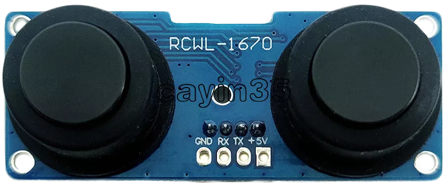
Image of RCWL-1670 ultrasonic sensor
Cirkit Designer LogoDesign with RCWL-1670 ultrasonic sensor in Cirkit Designer

Introduction

The RCWL-1670 ultrasonic sensor is a sophisticated motion detection component that integrates ultrasonic sensing with microwave radar technology. This sensor is capable of detecting motion through the measurement of changes in high-frequency radio waves and ultrasonic waves, offering a reliable method for sensing movement within its detection range. It is commonly used in applications such as automatic lighting, security systems, and industrial automation.

Explore Projects Built with RCWL-1670 ultrasonic sensor

Use Cirkit Designer to design, explore, and prototype these projects online. Some projects support real-time simulation. Click "Open Project" to start designing instantly!
Raspberry Pi Zero W-Based Ultrasonic Distance Measurement with RTC Time-Stamping
Image of Water Logger: A project utilizing RCWL-1670 ultrasonic sensor in a practical application
This circuit integrates a Raspberry Pi Zero W with an HC-SR04 Ultrasonic Sensor and an RTC DS3231 Real-Time Clock module. The Raspberry Pi is configured to communicate with the RTC via I2C (using GPIO2 for SDA and GPIO3 for SCL) to keep track of real-time, and it controls the ultrasonic sensor (triggering via GPIO23 and receiving echo signals on GPIO24) for distance measurement purposes. Power is supplied to the sensor and RTC from the Raspberry Pi's 5V and 3.3V pins respectively, with common ground connections.
Cirkit Designer LogoOpen Project in Cirkit Designer
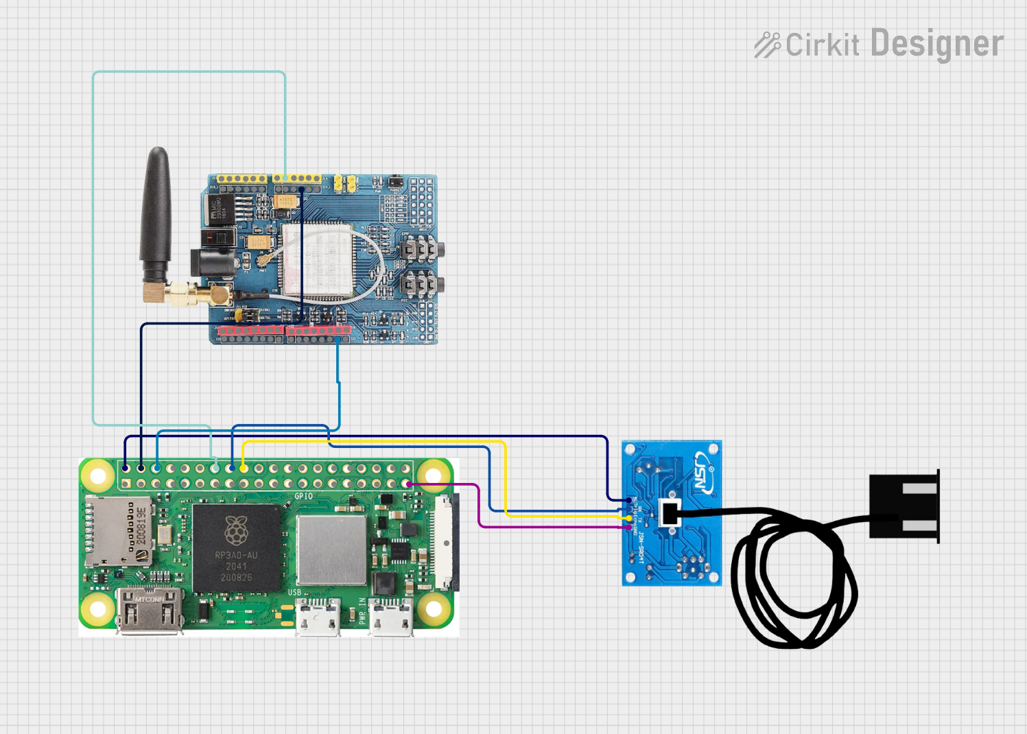
Raspberry Pi Zero W and GSM SIM900 Based Ultrasonic Distance Measurement System
Image of  ultrasonic sensor : A project utilizing RCWL-1670 ultrasonic sensor in a practical application
This circuit integrates a Raspberry Pi Zero W with a GSM SIM900 module and a JSN-SR04T Ultrasonic Sensor. The Raspberry Pi controls the ultrasonic sensor to measure distance and uses the GSM module for communication, potentially sending distance data over a cellular network.
Cirkit Designer LogoOpen Project in Cirkit Designer
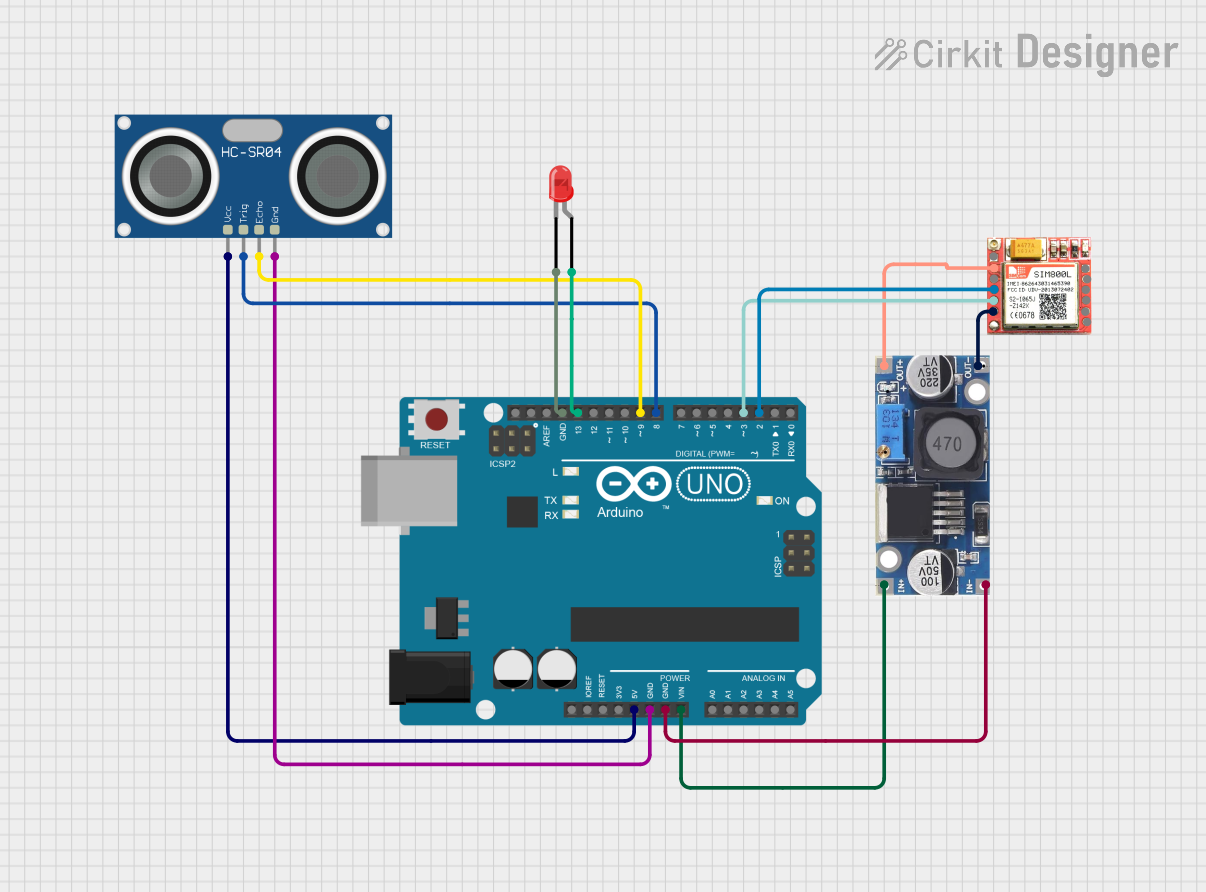
Arduino UNO-Based Ultrasonic Security System with SIM800L GSM Module
Image of Home security system: A project utilizing RCWL-1670 ultrasonic sensor in a practical application
This circuit features an Arduino UNO connected to an HC-SR04 ultrasonic sensor for distance measurement and a SIM800L GSM module for communication. The Arduino controls an LED, which lights up based on the distance detected by the ultrasonic sensor. When a certain distance threshold is exceeded, the Arduino uses the SIM800L module to make a phone call, indicating motion detection. A 48V to 5V converter supplies power to the SIM800L and the ultrasonic sensor.
Cirkit Designer LogoOpen Project in Cirkit Designer
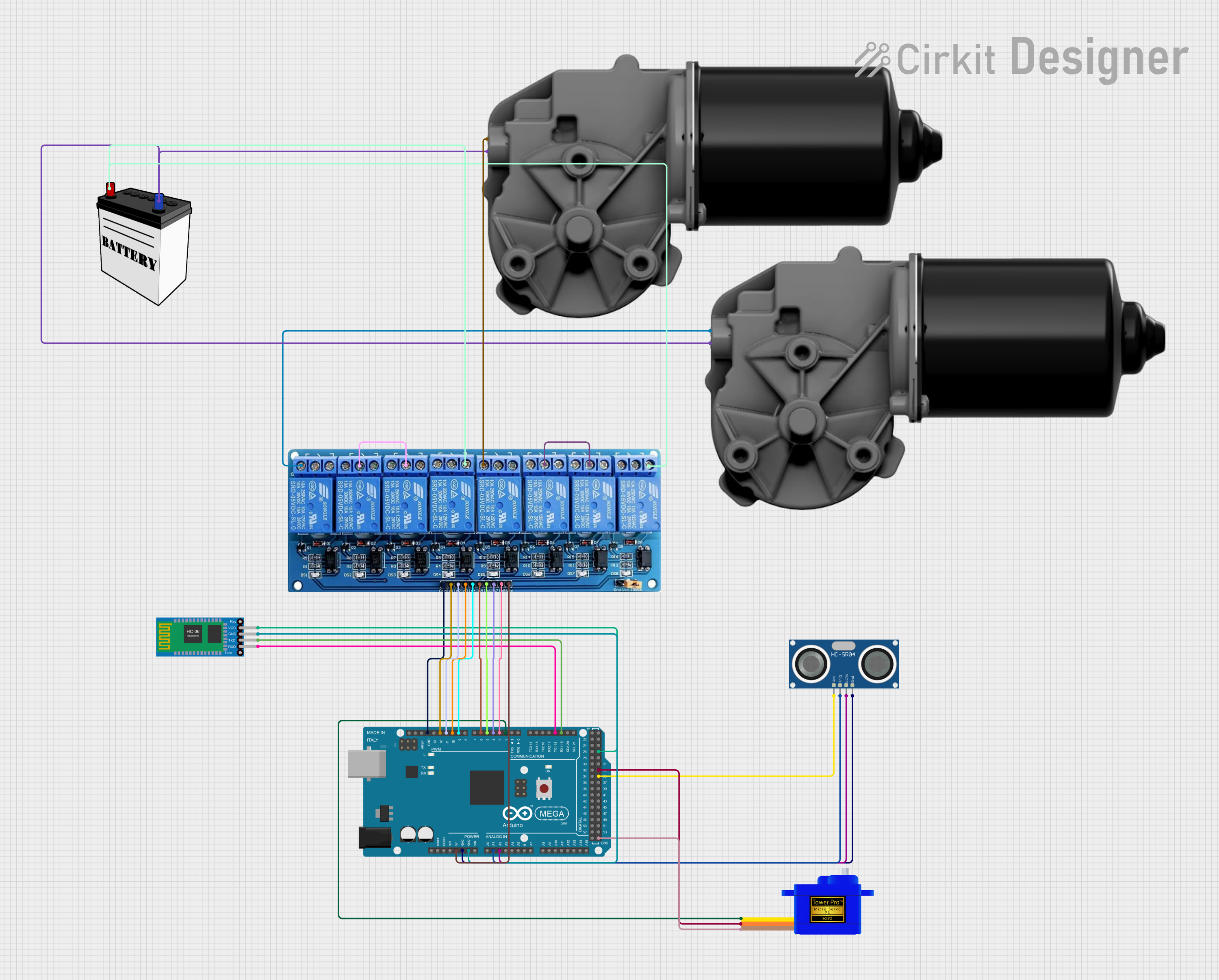
Arduino Mega 2560 Controlled Robot with Ultrasonic Obstacle Avoidance and Bluetooth Connectivity
Image of solar grass cutter : A project utilizing RCWL-1670 ultrasonic sensor in a practical application
This circuit features an Arduino Mega 2560 microcontroller interfaced with an HC-SR04 ultrasonic sensor for distance measurement, a Bluetooth HC-06 module for wireless communication, and a Servomotor SG90 for directional control. It controls two DC worm gear motors via a 5V 8-channel relay module, which is powered by a 12V battery. The system is designed for remote-controlled and autonomous obstacle avoidance, with the Arduino programmed to respond to Bluetooth commands and to automatically navigate around obstacles detected by the ultrasonic sensor.
Cirkit Designer LogoOpen Project in Cirkit Designer

Explore Projects Built with RCWL-1670 ultrasonic sensor

Use Cirkit Designer to design, explore, and prototype these projects online. Some projects support real-time simulation. Click "Open Project" to start designing instantly!
Image of Water Logger: A project utilizing RCWL-1670 ultrasonic sensor in a practical application
Raspberry Pi Zero W-Based Ultrasonic Distance Measurement with RTC Time-Stamping
This circuit integrates a Raspberry Pi Zero W with an HC-SR04 Ultrasonic Sensor and an RTC DS3231 Real-Time Clock module. The Raspberry Pi is configured to communicate with the RTC via I2C (using GPIO2 for SDA and GPIO3 for SCL) to keep track of real-time, and it controls the ultrasonic sensor (triggering via GPIO23 and receiving echo signals on GPIO24) for distance measurement purposes. Power is supplied to the sensor and RTC from the Raspberry Pi's 5V and 3.3V pins respectively, with common ground connections.
Cirkit Designer LogoOpen Project in Cirkit Designer
Image of  ultrasonic sensor : A project utilizing RCWL-1670 ultrasonic sensor in a practical application
Raspberry Pi Zero W and GSM SIM900 Based Ultrasonic Distance Measurement System
This circuit integrates a Raspberry Pi Zero W with a GSM SIM900 module and a JSN-SR04T Ultrasonic Sensor. The Raspberry Pi controls the ultrasonic sensor to measure distance and uses the GSM module for communication, potentially sending distance data over a cellular network.
Cirkit Designer LogoOpen Project in Cirkit Designer
Image of Home security system: A project utilizing RCWL-1670 ultrasonic sensor in a practical application
Arduino UNO-Based Ultrasonic Security System with SIM800L GSM Module
This circuit features an Arduino UNO connected to an HC-SR04 ultrasonic sensor for distance measurement and a SIM800L GSM module for communication. The Arduino controls an LED, which lights up based on the distance detected by the ultrasonic sensor. When a certain distance threshold is exceeded, the Arduino uses the SIM800L module to make a phone call, indicating motion detection. A 48V to 5V converter supplies power to the SIM800L and the ultrasonic sensor.
Cirkit Designer LogoOpen Project in Cirkit Designer
Image of solar grass cutter : A project utilizing RCWL-1670 ultrasonic sensor in a practical application
Arduino Mega 2560 Controlled Robot with Ultrasonic Obstacle Avoidance and Bluetooth Connectivity
This circuit features an Arduino Mega 2560 microcontroller interfaced with an HC-SR04 ultrasonic sensor for distance measurement, a Bluetooth HC-06 module for wireless communication, and a Servomotor SG90 for directional control. It controls two DC worm gear motors via a 5V 8-channel relay module, which is powered by a 12V battery. The system is designed for remote-controlled and autonomous obstacle avoidance, with the Arduino programmed to respond to Bluetooth commands and to automatically navigate around obstacles detected by the ultrasonic sensor.
Cirkit Designer LogoOpen Project in Cirkit Designer

Common Applications and Use Cases

  • Automated lighting control
  • Security and surveillance systems
  • Proximity detection for robotics
  • Industrial equipment motion sensing
  • Home automation systems

Technical Specifications

Key Technical Details

  • Operating Voltage: 4.5V to 28V
  • Operating Current: 2.8mA (typical)
  • Detection Angle: 360° (spherical)
  • Detection Range: 5 to 7 meters
  • Frequency: 3.2GHz microwave radar, 40kHz ultrasonic
  • Output Type: Digital signal (high/low)

Pin Configuration and Descriptions

Pin Number Name Description
1 VCC Power supply input (4.5V to 28V)
2 GND Ground connection
3 OUT Digital output signal (high when motion is detected)
4 CDS Light-dependent resistor (LDR) input for enabling operation in darkness

Usage Instructions

How to Use the Component in a Circuit

  1. Power Supply: Connect the VCC pin to a power source within the range of 4.5V to 28V. Ensure that the power supply can provide sufficient current for the sensor's operation.
  2. Ground Connection: Connect the GND pin to the ground of the power supply and your circuit's common ground.
  3. Output Signal: Connect the OUT pin to a digital input pin on a microcontroller, such as an Arduino, to read the sensor's output.
  4. LDR Input (Optional): If you want the sensor to operate only in low light conditions, connect a light-dependent resistor to the CDS pin.

Important Considerations and Best Practices

  • Ensure that the sensor is mounted in a stable position to avoid false triggers due to its own movement.
  • Avoid placing the sensor near objects that can reflect or absorb ultrasonic waves, as this can affect its accuracy.
  • The sensor's detection range can be influenced by environmental conditions such as temperature and humidity.
  • Use appropriate decoupling capacitors near the power supply pins to minimize power supply noise.

Troubleshooting and FAQs

Common Issues Users Might Face

  • False Triggers: Ensure that the sensor is not facing any moving objects within its detection range that could cause unintended activation.
  • No Output Signal: Check the power supply connections and ensure that the voltage is within the specified range. Also, verify that the microcontroller is correctly reading the digital output pin.
  • Limited Detection Range: Adjust the sensor's position or orientation to optimize its detection range. Environmental factors may also affect the range.

Solutions and Tips for Troubleshooting

  • If the sensor is not functioning as expected, double-check all connections and ensure that the power supply is stable and within the specified voltage range.
  • Use a multimeter to verify that the sensor is receiving power and that the output signal is changing when motion is detected.
  • For issues with the microcontroller interface, ensure that the correct digital pin is being used and that the microcontroller's code is properly configured to read the sensor's output.

Example Arduino Code

// Define the RCWL-1670 output pin
const int sensorPin = 2;

void setup() {
  // Initialize the sensor output pin as an input
  pinMode(sensorPin, INPUT);
  // Begin serial communication at 9600 baud rate
  Serial.begin(9600);
}

void loop() {
  // Read the sensor output
  int sensorValue = digitalRead(sensorPin);
  // If motion is detected, the output pin goes HIGH
  if (sensorValue == HIGH) {
    Serial.println("Motion detected!");
  } else {
    Serial.println("No motion detected.");
  }
  // Wait for a short period before reading again
  delay(500);
}

Note: The above code is a simple example to demonstrate how to interface the RCWL-1670 ultrasonic sensor with an Arduino UNO. The sensorPin should be connected to the OUT pin of the sensor, and the sensor should be powered according to the technical specifications. Adjust the delay as needed for your specific application.