How to Use Sensor de Campo Magnético: Examples, Pinouts, and Specs
Introduction
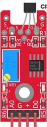
The KY-024 Magnetic Field Sensor, manufactured by Sensor, is a versatile and reliable component designed to detect the presence and strength of magnetic fields. It is widely used in applications such as navigation systems, robotics, industrial automation, and proximity detection. The sensor combines an analog output for precise measurements and a digital output for threshold-based detection, making it suitable for a variety of projects.
Explore Projects Built with Sensor de Campo Magnético

Explore Projects Built with Sensor de Campo Magnético
Technical Specifications
The KY-024 Magnetic Field Sensor is built with a Hall effect sensor and a potentiometer for sensitivity adjustment. Below are the key technical details:
Key Specifications
- Operating Voltage: 3.3V to 5V DC
- Output Type: Analog and Digital
- Sensitivity Adjustment: Onboard potentiometer
- Dimensions: 32mm x 14mm x 7mm
- Operating Temperature: -40°C to 85°C
- Detection Range: ±4mT (millitesla)
Pin Configuration and Descriptions
The KY-024 sensor has three pins for connectivity. The table below describes each pin:
| Pin | Name | Description |
|---|---|---|
| 1 | VCC | Power supply pin. Connect to 3.3V or 5V DC. |
| 2 | GND | Ground pin. Connect to the ground of the circuit. |
| 3 | DO | Digital output pin. Outputs HIGH or LOW based on the magnetic field threshold. |
| 4 | AO | Analog output pin. Provides a voltage proportional to the magnetic field. |
Usage Instructions
How to Use the KY-024 in a Circuit
- Power the Sensor: Connect the VCC pin to a 3.3V or 5V power source and the GND pin to the ground.
- Connect Outputs:
- Use the DO pin for digital output. This pin will output HIGH (1) when the magnetic field exceeds the threshold set by the potentiometer.
- Use the AO pin for analog output. This pin provides a voltage proportional to the detected magnetic field strength.
- Adjust Sensitivity: Use the onboard potentiometer to set the desired sensitivity for the digital output.
Example Circuit with Arduino UNO
Below is an example of how to connect the KY-024 sensor to an Arduino UNO:
- Connections:
- VCC → 5V on Arduino
- GND → GND on Arduino
- DO → Digital Pin 2 on Arduino
- AO → Analog Pin A0 on Arduino
Example Code
The following Arduino code reads both the digital and analog outputs of the KY-024 sensor:
// Define pin connections
const int digitalPin = 2; // Digital output pin from KY-024
const int analogPin = A0; // Analog output pin from KY-024

void setup() {
  pinMode(digitalPin, INPUT); // Set digital pin as input
  Serial.begin(9600); // Initialize serial communication
}

void loop() {
  // Read digital output
  int digitalValue = digitalRead(digitalPin);

  // Read analog output
  int analogValue = analogRead(analogPin);

  // Print values to the Serial Monitor
  Serial.print("Digital Output: ");
  Serial.print(digitalValue); // Print digital value (0 or 1)
  Serial.print(" | Analog Output: ");
  Serial.println(analogValue); // Print analog value (0-1023)

  delay(500); // Wait for 500ms before the next reading
}
Important Considerations and Best Practices
- Power Supply: Ensure the sensor is powered within its operating voltage range (3.3V to 5V). Exceeding this range may damage the sensor.
- Magnetic Interference: Avoid placing the sensor near strong electromagnetic sources, as they may interfere with readings.
- Sensitivity Adjustment: Use the potentiometer to fine-tune the digital output threshold for your specific application.
- Mounting: Secure the sensor in a stable position to avoid false readings caused by vibrations or movement.
Troubleshooting and FAQs
Common Issues and Solutions
No Output from the Sensor:
- Check the power connections (VCC and GND).
- Verify that the sensor is receiving the correct voltage (3.3V or 5V).
- Ensure the magnetic field is within the detection range of the sensor.
Digital Output Always HIGH or LOW:
- Adjust the potentiometer to change the sensitivity threshold.
- Verify that the magnetic field strength is sufficient to trigger the digital output.
Analog Output Not Changing:
- Ensure the AO pin is connected to an analog input pin on the microcontroller.
- Check for proper grounding and stable power supply.
Interference in Readings:
- Keep the sensor away from strong electromagnetic sources.
- Use shielded cables if the sensor is placed far from the microcontroller.
FAQs
Q: Can the KY-024 detect both north and south poles of a magnet?
A: Yes, the KY-024 can detect both poles of a magnet. The analog output will vary based on the strength and polarity of the magnetic field.
Q: How do I know if the digital output is triggered?
A: The onboard LED will light up when the digital output is HIGH, indicating that the magnetic field exceeds the set threshold.
Q: Can I use the KY-024 with a 3.3V microcontroller?
A: Yes, the KY-024 is compatible with 3.3V systems. Ensure the VCC pin is connected to a 3.3V power source.
Q: What is the maximum detection range of the KY-024?
A: The sensor can detect magnetic fields up to approximately ±4mT (millitesla).
By following this documentation, you can effectively integrate the KY-024 Magnetic Field Sensor into your projects and troubleshoot any issues that arise.