How to Use 1.3 OLED Display Module: Examples, Pinouts, and Specs
Introduction
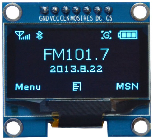
The 1.3" OLED Display Module is a compact and versatile screen suitable for adding visual output to electronic projects. OLED stands for Organic Light Emitting Diode, a technology known for its high contrast ratios, deep blacks, and wide viewing angles. This module is commonly used in wearable devices, small instruments, and any application where a small yet clear display is required.
Explore Projects Built with 1.3 OLED Display Module


Explore Projects Built with 1.3 OLED Display Module
Common Applications and Use Cases
- Wearable devices (e.g., smartwatches, fitness trackers)
- Portable instruments (e.g., multimeters, handheld gaming devices)
- User interfaces for small-scale projects
- Display for sensor data or system status
Technical Specifications
Key Technical Details
- Display Size: 1.3 inches
- Resolution: 128x64 pixels
- Color: Monochrome (White/Blue/Yellow-Blue)
- Interface: I2C/SPI (depending on the model)
- Operating Voltage: 3.3V - 5V
- Driver IC: SSD1306/SH1106 (model-dependent)
Pin Configuration and Descriptions
| Pin Number | Pin Name | Description |
|---|---|---|
| 1 | GND | Ground |
| 2 | VCC | Power supply (3.3V - 5V) |
| 3 | SCL | Serial Clock Line (I2C) or SPI Clock (SPI) |
| 4 | SDA | Serial Data Line (I2C) or SPI Data (SPI) |
| 5 | RES | Reset pin (optional for some models) |
| 6 | DC | Data/Command (SPI mode only) |
| 7 | CS | Chip Select (SPI mode only) |
Usage Instructions
How to Use the Component in a Circuit
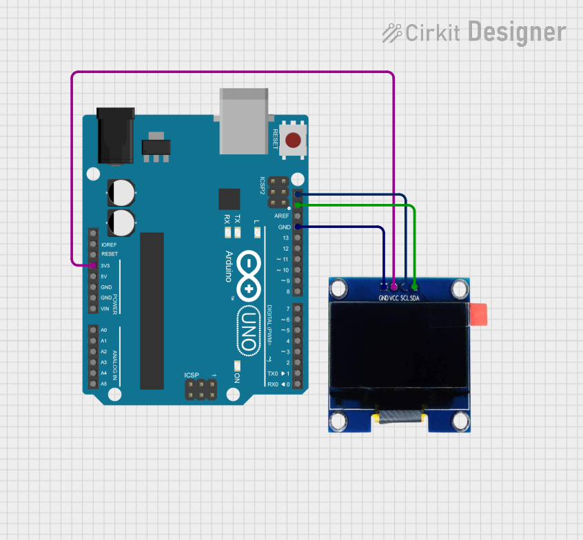
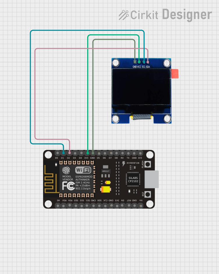
- Power Connections: Connect the VCC pin to a 3.3V or 5V power supply, and the GND pin to the ground of your circuit.
- Data Connections (I2C): Connect the SCL and SDA pins to the corresponding I2C clock and data lines on your microcontroller.
- Data Connections (SPI): Connect SCL, SDA, DC, and CS to the SPI clock, data in, data/command, and chip select pins on your microcontroller, respectively.
- Reset (Optional): The RES pin can be connected to a digital pin on your microcontroller if software control of the display reset is required.
Important Considerations and Best Practices
- Ensure that the power supply voltage matches the module's requirements.
- Use pull-up resistors on the I2C lines if they are not built into the module.
- For SPI mode, ensure that the correct data/command and chip select lines are used.
- Initialize the display with the correct driver (SSD1306 or SH1106) in your code.
Example Code for Arduino UNO
#include <Wire.h> // Include Wire library for I2C
#include <Adafruit_GFX.h> // Include core graphics library
#include <Adafruit_SSD1306.h> // Include Adafruit SSD1306 library

#define SCREEN_WIDTH 128 // OLED display width, in pixels
#define SCREEN_HEIGHT 64 // OLED display height, in pixels

// Declaration for an SSD1306 display connected to I2C (SCL, SDA pins)
#define OLED_RESET     -1 // Reset pin # (or -1 if sharing Arduino reset pin)
Adafruit_SSD1306 display(SCREEN_WIDTH, SCREEN_HEIGHT, &Wire, OLED_RESET);

void setup() {
  // Initialize with the I2C addr 0x3C (for the 128x64)
  if(!display.begin(SSD1306_SWITCHCAPVCC, 0x3C)) {
    Serial.println(F("SSD1306 allocation failed"));
    for(;;); // Don't proceed, loop forever
  }

  // Clear the buffer
  display.clearDisplay();

  // Draw a single pixel in white
  display.drawPixel(10, 10, WHITE);

  // Display the drawing
  display.display();
}

void loop() {
  // Nothing here for this simple example
}
Troubleshooting and FAQs
Common Issues Users Might Face
- Display Not Powering On: Check the power connections and ensure the voltage is within the specified range.
- No Data on Display: Verify that the I2C/SPI connections are correct and that the correct communication protocol is selected in your code.
- Garbled or Incomplete Output: Ensure that the display is properly initialized in your code and that the correct driver (SSD1306 or SH1106) is being used.
Solutions and Tips for Troubleshooting
- Double-check wiring, especially the power and data lines.
- Use example code to test the display functionality before integrating it into your project.
- Consult the datasheet for the driver IC to understand the initialization process and command set.
FAQs
Q: Can I use this display with a 5V system? A: Yes, most 1.3" OLED modules are 5V tolerant, but always check the specifications.
Q: How do I know if my display is using the SSD1306 or SH1106 driver? A: This information is usually provided by the vendor. If not, you may need to test with both drivers or consult the module's datasheet.
Q: Can I display images on the OLED? A: Yes, the Adafruit GFX library allows you to display bitmap images on the OLED.
Q: Is it possible to use multiple OLED displays with an Arduino? A: Yes, you can use multiple displays by assigning different addresses for I2C or different chip select lines for SPI.