How to Use PZEM-004T V3: Examples, Pinouts, and Specs
Introduction
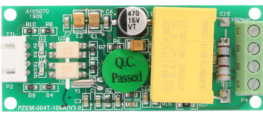
The PZEM-004T V3, manufactured by Peacefair, is a multifunctional energy monitoring module designed for AC circuits. It is capable of measuring key electrical parameters such as voltage, current, power, energy, and frequency. The module communicates via UART (Universal Asynchronous Receiver-Transmitter), making it easy to integrate with microcontrollers, such as Arduino, Raspberry Pi, and other embedded systems.
Explore Projects Built with PZEM-004T V3


Explore Projects Built with PZEM-004T V3
Common Applications and Use Cases
- Home energy monitoring systems
- Industrial power consumption analysis
- Smart energy meters
- Renewable energy systems (e.g., solar or wind power monitoring)
- IoT-based energy management solutions
Technical Specifications
The following table outlines the key technical specifications of the PZEM-004T V3:
| Parameter | Specification |
|---|---|
| Voltage Range | 80V to 260V AC |
| Current Range | 0A to 100A (with external current transformer) |
| Power Range | 0W to 22kW |
| Energy Range | 0kWh to 9999kWh |
| Frequency Range | 45Hz to 65Hz |
| Communication Protocol | UART (9600 baud rate, 8N1 format) |
| Power Supply | 5V DC (external power source required) |
| Accuracy | ±0.5% |
| Dimensions | 48mm x 23mm x 15mm |
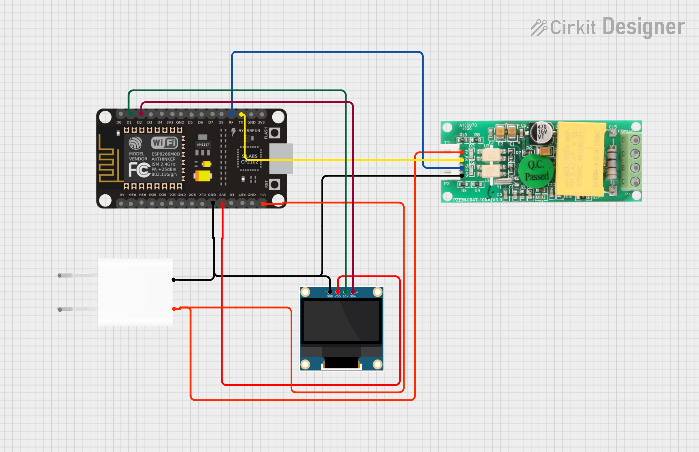
Pin Configuration and Descriptions
The PZEM-004T V3 module has a 4-pin interface for communication and power, as well as terminals for AC input and the current transformer (CT). The pin configuration is as follows:
UART and Power Pins
| Pin | Name | Description |
|---|---|---|
| 1 | VCC | 5V DC power input |
| 2 | GND | Ground |
| 3 | TX | UART Transmit (connect to RX of microcontroller) |
| 4 | RX | UART Receive (connect to TX of microcontroller) |
AC Input and CT Terminals
| Terminal | Name | Description |
|---|---|---|
| AC IN | L (Line) | Connect to the live wire of the AC circuit |
| AC IN | N (Neutral) | Connect to the neutral wire of the AC circuit |
| CT | S1, S2 | Connect to the external current transformer |
Usage Instructions
How to Use the PZEM-004T V3 in a Circuit
- Power the Module: Connect the VCC and GND pins to a 5V DC power source.
- Connect the AC Circuit:
- Attach the live (L) and neutral (N) wires of the AC circuit to the respective AC IN terminals.
- Ensure proper insulation and safety precautions when working with high-voltage AC circuits.
- Connect the Current Transformer (CT):
- Place the CT around the live wire of the AC circuit.
- Connect the CT wires to the S1 and S2 terminals on the module.
- Establish UART Communication:
- Connect the TX pin of the module to the RX pin of the microcontroller.
- Connect the RX pin of the module to the TX pin of the microcontroller.
- Program the Microcontroller:
- Use the UART protocol to send commands and receive data from the module.
- Refer to the manufacturer's communication protocol documentation for command details.
Important Considerations and Best Practices
- Safety First: Always ensure the AC circuit is powered off before making connections.
- Current Transformer Orientation: Ensure the CT is properly oriented around the live wire for accurate current measurement.
- Baud Rate: The module operates at a fixed baud rate of 9600. Ensure your microcontroller is configured accordingly.
- Power Supply: Use a stable 5V DC power source to avoid communication errors or inaccurate readings.
- Isolation: Avoid direct contact with the AC terminals to prevent electric shock.
Example: Using PZEM-004T V3 with Arduino UNO
Below is an example Arduino sketch to read data from the PZEM-004T V3 module:
#include <SoftwareSerial.h>

// Define RX and TX pins for SoftwareSerial
SoftwareSerial pzemSerial(10, 11); // RX = Pin 10, TX = Pin 11

void setup() {
  Serial.begin(9600); // Initialize Serial Monitor
  pzemSerial.begin(9600); // Initialize communication with PZEM-004T V3

  Serial.println("PZEM-004T V3 Energy Monitor");
}

void loop() {
  // Send a command to request data (example command for voltage)
  byte request[] = {0xB0, 0xC0, 0xA8, 0x01, 0x01}; // Replace with actual command
  pzemSerial.write(request, sizeof(request));

  // Wait for response
  delay(100);

  // Read response from PZEM-004T V3
  while (pzemSerial.available()) {
    byte response = pzemSerial.read();
    Serial.print(response, HEX); // Print response in HEX format
    Serial.print(" ");
  }
  Serial.println();

  delay(1000); // Wait 1 second before next request
}
Notes:
- Replace the
requestarray with the appropriate command for the parameter you want to measure (e.g., voltage, current, power). - Use a library like PZEM004T for easier integration and command handling.
Troubleshooting and FAQs
Common Issues and Solutions
No Data Received from the Module:
- Ensure the TX and RX pins are correctly connected (crossed: TX to RX, RX to TX).
- Verify the baud rate is set to 9600 in your microcontroller code.
- Check the power supply to ensure the module is receiving 5V DC.
Inaccurate Measurements:
- Verify the current transformer (CT) is properly clamped around the live wire.
- Ensure the AC IN terminals are securely connected to the live and neutral wires.
Communication Errors:
- Use shorter wires for UART communication to reduce noise.
- Add pull-up resistors to the TX and RX lines if necessary.
Module Not Powering On:
- Check the VCC and GND connections.
- Ensure the power supply provides a stable 5V DC output.
FAQs
Q: Can the PZEM-004T V3 measure DC circuits?
A: No, the module is designed specifically for AC circuits and cannot measure DC voltage or current.
Q: What is the maximum current the module can measure?
A: The module can measure up to 100A when used with the provided current transformer.
Q: Can I use multiple PZEM-004T V3 modules with a single microcontroller?
A: Yes, you can connect multiple modules by assigning unique addresses to each module using the manufacturer's protocol.
Q: Is the module compatible with 3.3V microcontrollers?
A: The module requires a 5V power supply, but the UART pins are 3.3V logic compatible. Use a level shifter if needed for reliable communication.
Q: How do I reset the energy counter?
A: Send the appropriate reset command via UART as specified in the manufacturer's protocol documentation.