
How to Use DI-808 Databucket: Examples, Pinouts, and Specs
 Design with DI-808 Databucket in Cirkit Designer
Introduction
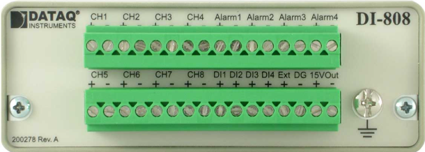
The DI-808 Databucket by DATAQ Instruments (Part ID: DI-808-32) is a versatile data acquisition and control device designed for industrial applications. It features multiple input/output channels, enabling users to monitor and control a wide range of sensors and actuators. With its robust design and high precision, the DI-808 is ideal for applications such as process automation, environmental monitoring, and industrial equipment control.
Explore Projects Built with DI-808 Databucket
 Open Project in Cirkit Designer
 Open Project in Cirkit Designer
 Open Project in Cirkit Designer
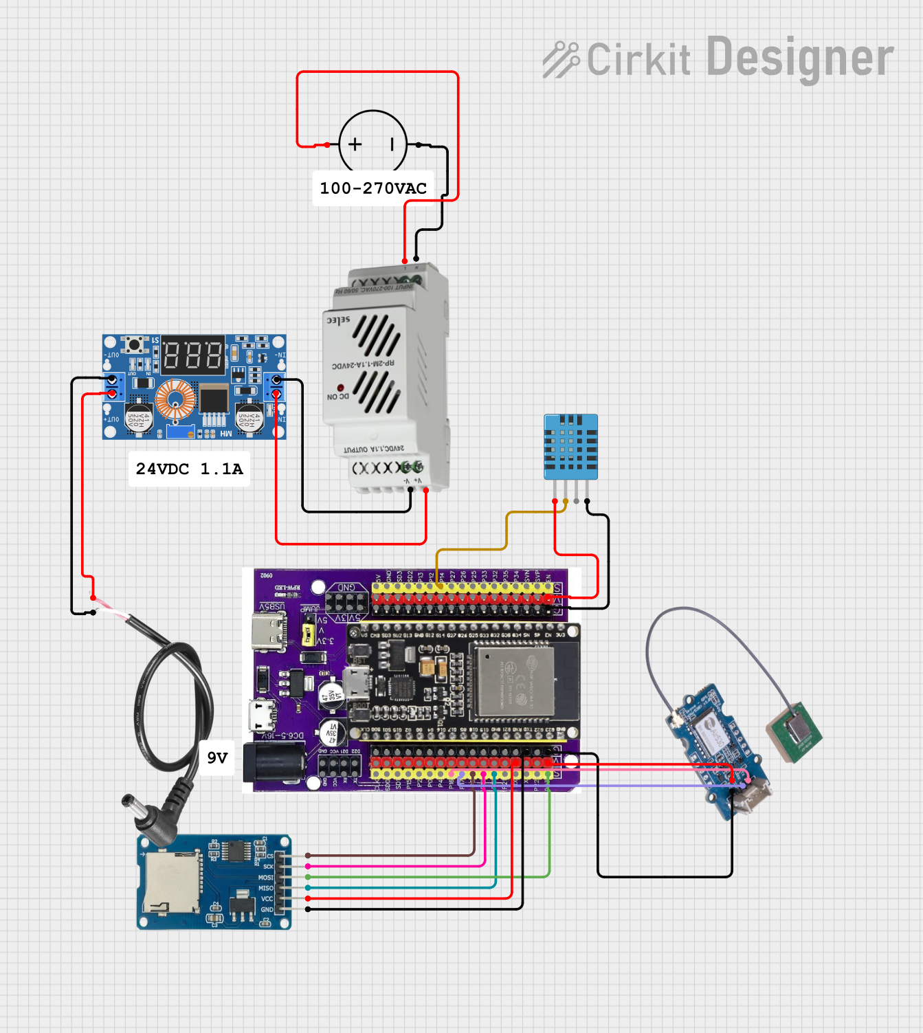 Open Project in Cirkit Designer
Explore Projects Built with DI-808 Databucket
Open Project in Cirkit DesignerOpen Project in Cirkit DesignerOpen Project in Cirkit DesignerOpen Project in Cirkit DesignerCommon Applications
- Industrial process monitoring and control
- Environmental data logging
- Sensor data acquisition
- Actuator control in automated systems
- Research and development in industrial environments
Technical Specifications
Key Technical Details
| Parameter | Specification |
|---|---|
| Input Channels | 8 analog inputs, 8 digital inputs |
| Output Channels | 8 digital outputs |
| Analog Input Resolution | 12-bit |
| Analog Input Range | 0–10 V |
| Digital Input Voltage | 0–24 V (logic high: >10 V, low: <2 V) |
| Digital Output Voltage | 0–24 V (max current: 500 mA per channel) |
| Communication Interface | USB 2.0, RS-485 |
| Power Supply | 12–24 V DC |
| Operating Temperature | -20°C to 60°C |
| Dimensions | 150 mm x 100 mm x 50 mm |
| Weight | 500 g |
Pin Configuration and Descriptions
Analog Input Channels
| Pin Number | Description | Notes |
|---|---|---|
| AI1 | Analog Input Channel 1 | 0–10 V input range |
| AI2 | Analog Input Channel 2 | 0–10 V input range |
| AI3 | Analog Input Channel 3 | 0–10 V input range |
| AI4 | Analog Input Channel 4 | 0–10 V input range |
| AI5 | Analog Input Channel 5 | 0–10 V input range |
| AI6 | Analog Input Channel 6 | 0–10 V input range |
| AI7 | Analog Input Channel 7 | 0–10 V input range |
| AI8 | Analog Input Channel 8 | 0–10 V input range |
Digital Input/Output Channels
| Pin Number | Description | Notes |
|---|---|---|
| DI1 | Digital Input Channel 1 | Logic high: >10 V, low: <2 V |
| DI2 | Digital Input Channel 2 | Logic high: >10 V, low: <2 V |
| DI3 | Digital Input Channel 3 | Logic high: >10 V, low: <2 V |
| DI4 | Digital Input Channel 4 | Logic high: >10 V, low: <2 V |
| DI5 | Digital Input Channel 5 | Logic high: >10 V, low: <2 V |
| DI6 | Digital Input Channel 6 | Logic high: >10 V, low: <2 V |
| DI7 | Digital Input Channel 7 | Logic high: >10 V, low: <2 V |
| DI8 | Digital Input Channel 8 | Logic high: >10 V, low: <2 V |
| DO1 | Digital Output Channel 1 | Max current: 500 mA |
| DO2 | Digital Output Channel 2 | Max current: 500 mA |
| DO3 | Digital Output Channel 3 | Max current: 500 mA |
| DO4 | Digital Output Channel 4 | Max current: 500 mA |
| DO5 | Digital Output Channel 5 | Max current: 500 mA |
| DO6 | Digital Output Channel 6 | Max current: 500 mA |
| DO7 | Digital Output Channel 7 | Max current: 500 mA |
| DO8 | Digital Output Channel 8 | Max current: 500 mA |
Usage Instructions
How to Use the DI-808 in a Circuit
- Power Supply: Connect a 12–24 V DC power supply to the power input terminals.
- Analog Inputs: Connect sensors with 0–10 V output to the analog input channels (AI1–AI8).
- Digital Inputs: Connect digital sensors or switches to the digital input channels (DI1–DI8). Ensure the input voltage is within the 0–24 V range.
- Digital Outputs: Connect actuators (e.g., relays, motors) to the digital output channels (DO1–DO8). Ensure the load does not exceed 500 mA per channel.
- Communication: Use the USB or RS-485 interface to connect the DI-808 to a computer or PLC for data acquisition and control.
Important Considerations
- Ensure proper grounding to avoid noise interference in analog signals.
- Use appropriate pull-up or pull-down resistors for digital inputs if required.
- Avoid exceeding the maximum voltage and current ratings for all channels.
- Use shielded cables for analog inputs in noisy environments.
Example: Connecting to an Arduino UNO
The DI-808 can be interfaced with an Arduino UNO via the RS-485 communication interface. Below is an example Arduino sketch for reading data from the DI-808.
#include <SoftwareSerial.h>

// Define RS-485 communication pins
#define RX_PIN 10  // Arduino pin connected to DI-808 TX
#define TX_PIN 11  // Arduino pin connected to DI-808 RX

SoftwareSerial rs485(RX_PIN, TX_PIN);

void setup() {
  Serial.begin(9600);       // Initialize serial monitor
  rs485.begin(9600);        // Initialize RS-485 communication
  Serial.println("DI-808 Communication Initialized");
}

void loop() {
  // Send a command to request data from the DI-808
  rs485.write("READ_AI1\n");  // Example command to read Analog Input 1

  delay(100);  // Wait for the DI-808 to respond

  // Check if data is available from the DI-808
  if (rs485.available()) {
    String response = "";
    while (rs485.available()) {
      char c = rs485.read();
      response += c;
    }
    Serial.print("DI-808 Response: ");
    Serial.println(response);  // Print the response to the serial monitor
  }

  delay(1000);  // Wait before sending the next command
}
Troubleshooting and FAQs
Common Issues
No Communication with the DI-808
- Solution: Verify the USB or RS-485 connection. Ensure the correct communication protocol and baud rate are configured.
Analog Input Readings Are Incorrect
- Solution: Check the sensor connections and ensure the input voltage is within the 0–10 V range. Verify proper grounding.
Digital Outputs Not Working
- Solution: Ensure the connected load does not exceed 500 mA per channel. Verify the output channel is correctly activated in the control software.
Device Overheating
- Solution: Ensure adequate ventilation and avoid exceeding the maximum current ratings for digital outputs.
FAQs
Q: Can the DI-808 be used with wireless communication?
A: Yes, by connecting a wireless RS-485 module, the DI-808 can communicate wirelessly.Q: What software is compatible with the DI-808?
A: The DI-808 is compatible with DATAQ Instruments' software suite and third-party applications that support USB or RS-485 communication.Q: Can I use the DI-808 in outdoor environments?
A: The DI-808 is not weatherproof. Use an appropriate enclosure for outdoor applications.