How to Use Adafruit MAX31856 Thermocouple Amp: Examples, Pinouts, and Specs
Introduction
The Adafruit MAX31856 Thermocouple Amplifier is a sophisticated electronic component designed to interface with thermocouples, providing precise temperature readings. Thermocouples are sensors that measure temperature by utilizing the Seebeck effect, which generates a voltage proportional to the temperature difference between two different metals. The MAX31856 chip amplifies this small voltage, digitizes it, and provides a digital readout that can be interpreted by a microcontroller such as an Arduino UNO. This component is commonly used in applications requiring high-precision temperature monitoring, such as industrial systems, scientific instruments, and consumer appliances.
Explore Projects Built with Adafruit MAX31856 Thermocouple Amp
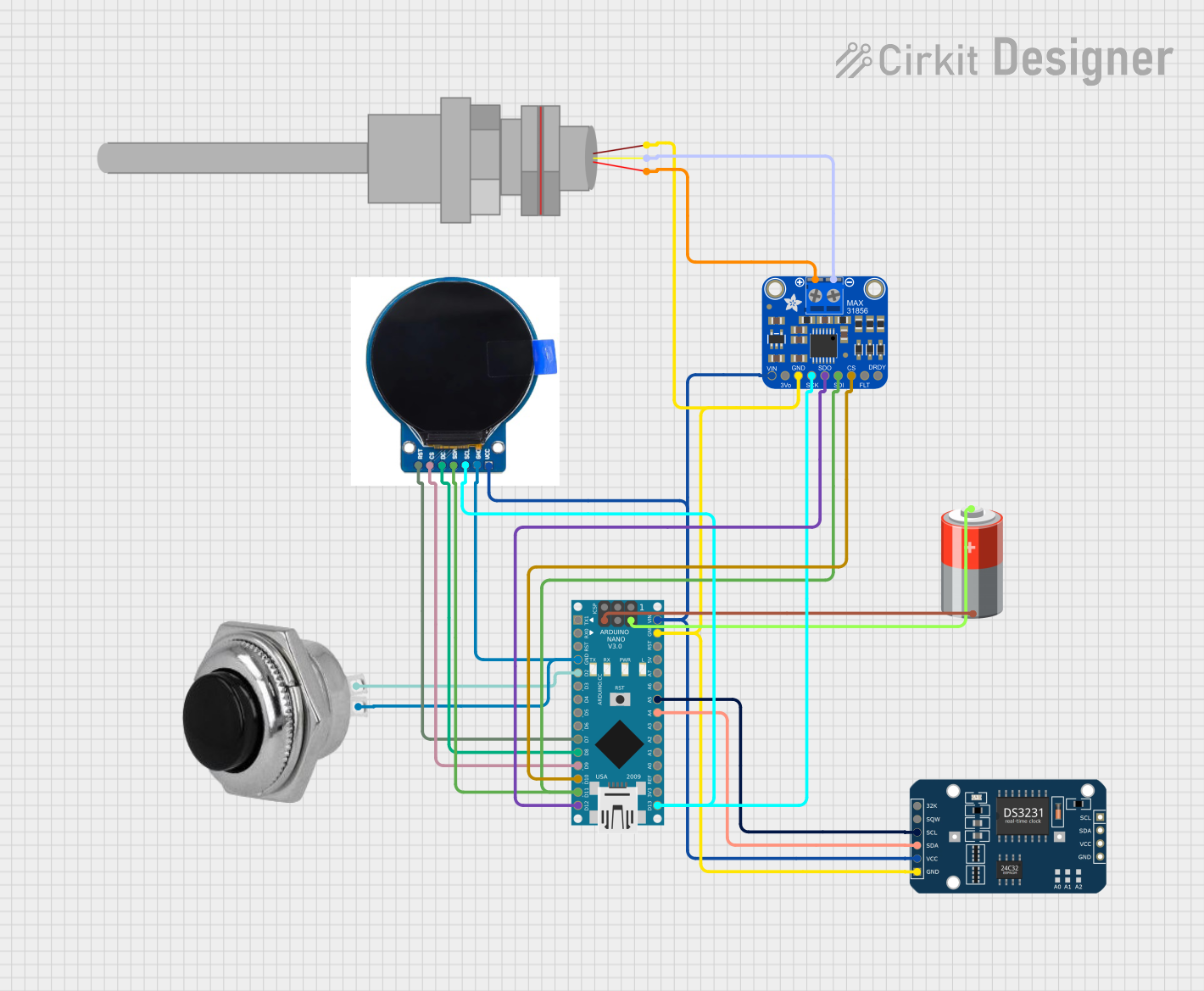
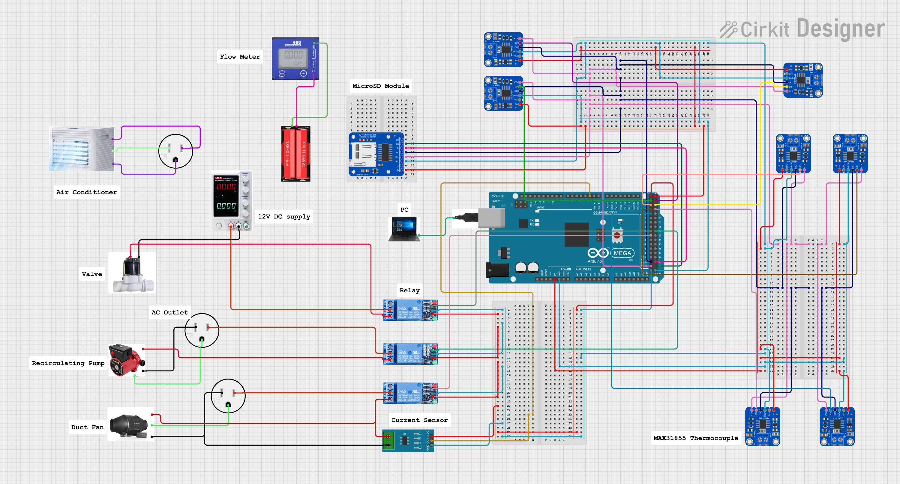

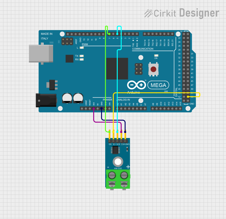
Explore Projects Built with Adafruit MAX31856 Thermocouple Amp
Technical Specifications
Key Technical Details
- Supply Voltage: 3.3V to 5V
- Temperature Resolution: 0.0078125°C
- Temperature Range: -200°C to +1350°C (dependent on thermocouple type)
- Interface: SPI
- Thermocouple Types Supported: B, E, J, K, N, R, S, T
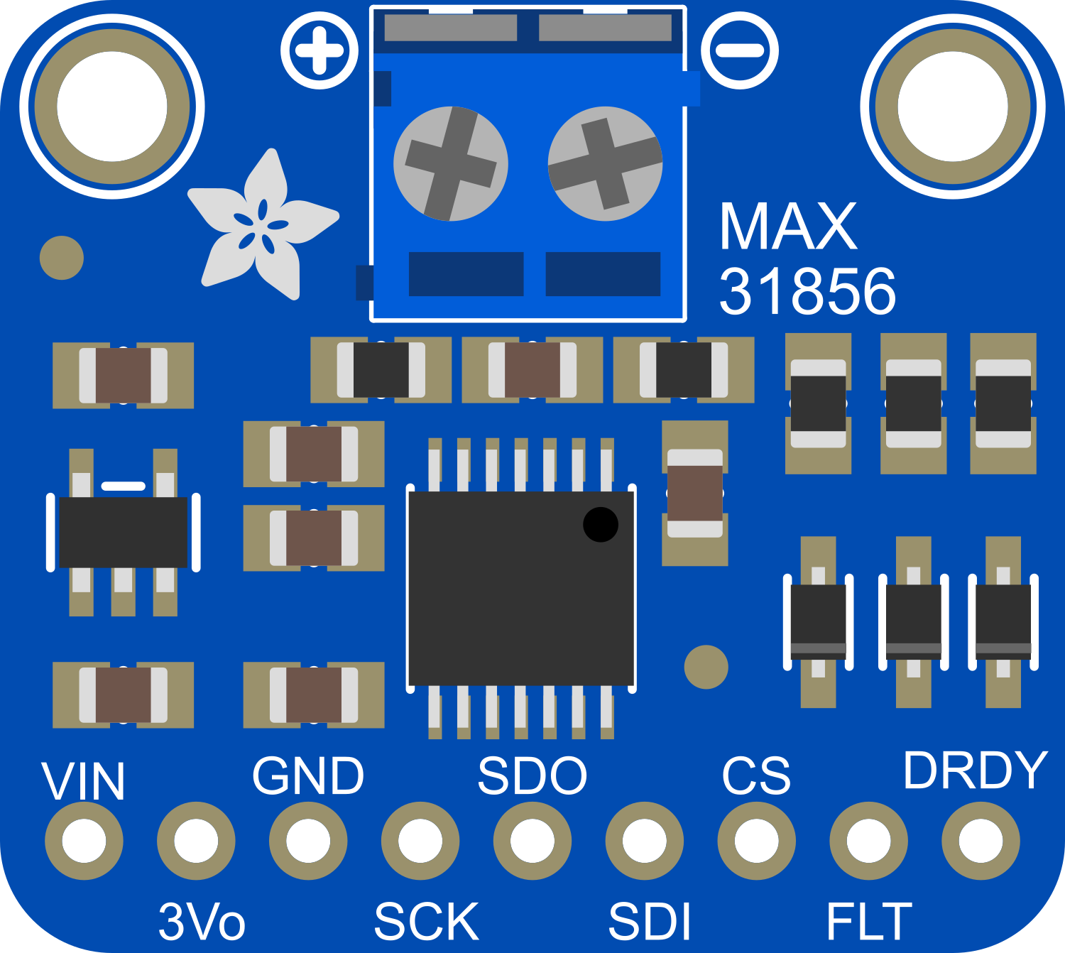
Pin Configuration and Descriptions
| Pin Number | Name | Description |
|---|---|---|
| 1 | VIN | Power supply (3.3V to 5V) |
| 2 | GND | Ground |
| 3 | DO | SPI Data Output to microcontroller |
| 4 | DI | SPI Data Input from microcontroller |
| 5 | CLK | SPI Clock |
| 6 | CS | SPI Chip Select |
| 7 | RDY | Ready pin, goes low when conversion is complete |
| 8 | TC+ | Thermocouple positive connection |
| 9 | TC- | Thermocouple negative connection |
Usage Instructions
How to Use the Component in a Circuit
- Power Connections: Connect the VIN pin to a 3.3V or 5V supply, and the GND pin to the ground on your microcontroller board.
- SPI Connections: Connect the DO, DI, CLK, and CS pins to the corresponding SPI pins on your microcontroller.
- Thermocouple Connections: Attach the thermocouple leads to the TC+ and TC- pins, ensuring correct polarity.
- Ready Pin: Optionally, connect the RDY pin to a digital input on your microcontroller to detect when a temperature conversion is complete.
Important Considerations and Best Practices
- Ensure that the thermocouple wires are connected with the correct polarity to the amplifier.
- Use twisted pair wires for the thermocouple leads to reduce noise and improve accuracy.
- Keep the thermocouple leads as short as possible to minimize potential interference.
- Avoid placing the amplifier near high-temperature sources to prevent self-heating and inaccurate readings.
Example Code for Arduino UNO
#include <SPI.h>
#include <Adafruit_MAX31856.h>

// Use hardware SPI, specify CS pin
Adafruit_MAX31856 maxthermo = Adafruit_MAX31856(10);

void setup() {
  Serial.begin(9600);
  maxthermo.begin();
  maxthermo.setThermocoupleType(MAX31856_TCTYPE_K);
}

void loop() {
  // Read temperature
  Serial.print("Temperature: ");
  Serial.println(maxthermo.readThermocoupleTemperature());
  // Wait for 1 second before reading again
  delay(1000);
}
Troubleshooting and FAQs
Common Issues
- Incorrect Temperature Readings: Ensure that the thermocouple is properly connected with the correct polarity and that the correct thermocouple type is set in the software.
- No Data on SPI: Check the wiring of the SPI pins and ensure that the correct CS pin is being used in the code.
- Device Not Powering On: Verify that the power supply is within the specified voltage range and that the connections are secure.
Solutions and Tips for Troubleshooting
- If you encounter noise in the temperature readings, consider using a filter capacitor across the power supply pins near the MAX31856.
- Ensure that the SPI bus is not shared with other devices that might interfere with the communication.
- Use the RDY pin to ensure that you read the temperature only after a conversion is complete.
FAQs
Q: Can I use the MAX31856 with a 3.3V microcontroller? A: Yes, the MAX31856 is compatible with both 3.3V and 5V logic levels.
Q: How do I calibrate the thermocouple amplifier? A: The MAX31856 is factory-calibrated, but you can perform a system calibration by comparing the readings to a known temperature reference and applying an offset in your code if necessary.
Q: What types of thermocouples can I use with this amplifier?
A: The MAX31856 supports multiple thermocouple types including B, E, J, K, N, R, S, and T. You must set the correct type in your code using the setThermocoupleType() function.
Q: How long can the thermocouple wires be? A: The length of the thermocouple wires can vary, but it's recommended to keep them as short as possible to reduce noise and potential signal degradation. If longer wires are necessary, use shielded twisted pair cables.