How to Use RS485 to TTL: Examples, Pinouts, and Specs
Introduction
The RS485 to TTL converter is a versatile electronic component designed to bridge the gap between RS485 serial communication devices and TTL (Transistor-Transistor Logic) level devices. RS485 is a robust communication standard commonly used for long-distance, noise-resistant data transmission, while TTL operates at lower voltage levels suitable for microcontrollers and other digital systems. This converter ensures seamless communication between these two standards, making it an essential tool for industrial automation, IoT applications, and embedded systems.
Explore Projects Built with RS485 to TTL


Explore Projects Built with RS485 to TTL
Common Applications and Use Cases
- Industrial automation systems for long-distance communication
- Connecting microcontrollers (e.g., Arduino, Raspberry Pi) to RS485 networks
- Home automation and building management systems
- Data acquisition systems and sensor networks
- Serial communication in noisy environments
Technical Specifications
The RS485 to TTL converter typically features the following specifications:
| Parameter | Value |
|---|---|
| Operating Voltage | 3.3V to 5V |
| Communication Standard | RS485 (differential) to TTL (single-ended) |
| Baud Rate | Up to 115200 bps (varies by model) |
| Maximum Distance | Up to 1200 meters (RS485 side) |
| Operating Temperature | -40°C to 85°C |
| Dimensions | Varies by model (e.g., 40mm x 15mm) |
Pin Configuration and Descriptions
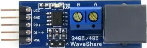
The RS485 to TTL converter typically has the following pinout:
| Pin Name | Description |
|---|---|
| VCC | Power input (3.3V or 5V, depending on the module) |
| GND | Ground connection |
| RO | Receiver Output (TTL level, data received from RS485 bus) |
| DI | Driver Input (TTL level, data to be transmitted to RS485 bus) |
| DE | Driver Enable (active high, enables RS485 transmission) |
| RE | Receiver Enable (active low, enables RS485 reception) |
| A (D+) | RS485 differential line A (non-inverting) |
| B (D-) | RS485 differential line B (inverting) |
Note: Some modules may combine DE and RE into a single control pin for simplicity.
Usage Instructions
How to Use the RS485 to TTL Converter in a Circuit
- Power the Module: Connect the VCC pin to a 3.3V or 5V power source and the GND pin to ground.
- Connect RS485 Lines: Attach the A (D+) and B (D-) pins to the RS485 bus. Ensure proper polarity.
- Connect TTL Lines:
- Connect the RO pin to the RX pin of your microcontroller (for receiving data).
- Connect the DI pin to the TX pin of your microcontroller (for transmitting data).
- Control Pins:
- If DE and RE are separate, connect DE to a GPIO pin and set it high for transmission.
- Connect RE to a GPIO pin and set it low for reception.
- If DE and RE are combined, toggle the control pin high for transmission and low for reception.
- Termination Resistor: If the RS485 bus is at the end of the line, add a 120-ohm termination resistor between A and B.
Important Considerations and Best Practices
- Voltage Compatibility: Ensure the module's VCC matches the logic level of your microcontroller (3.3V or 5V).
- Bus Termination: Use termination resistors at both ends of the RS485 bus to prevent signal reflections.
- Pull-Up/Pull-Down Resistors: Add pull-up and pull-down resistors on the A and B lines to maintain a known idle state.
- Noise Reduction: Use twisted-pair cables for RS485 connections to minimize electromagnetic interference.
- Baud Rate Matching: Ensure the baud rate of all devices on the RS485 bus matches for proper communication.
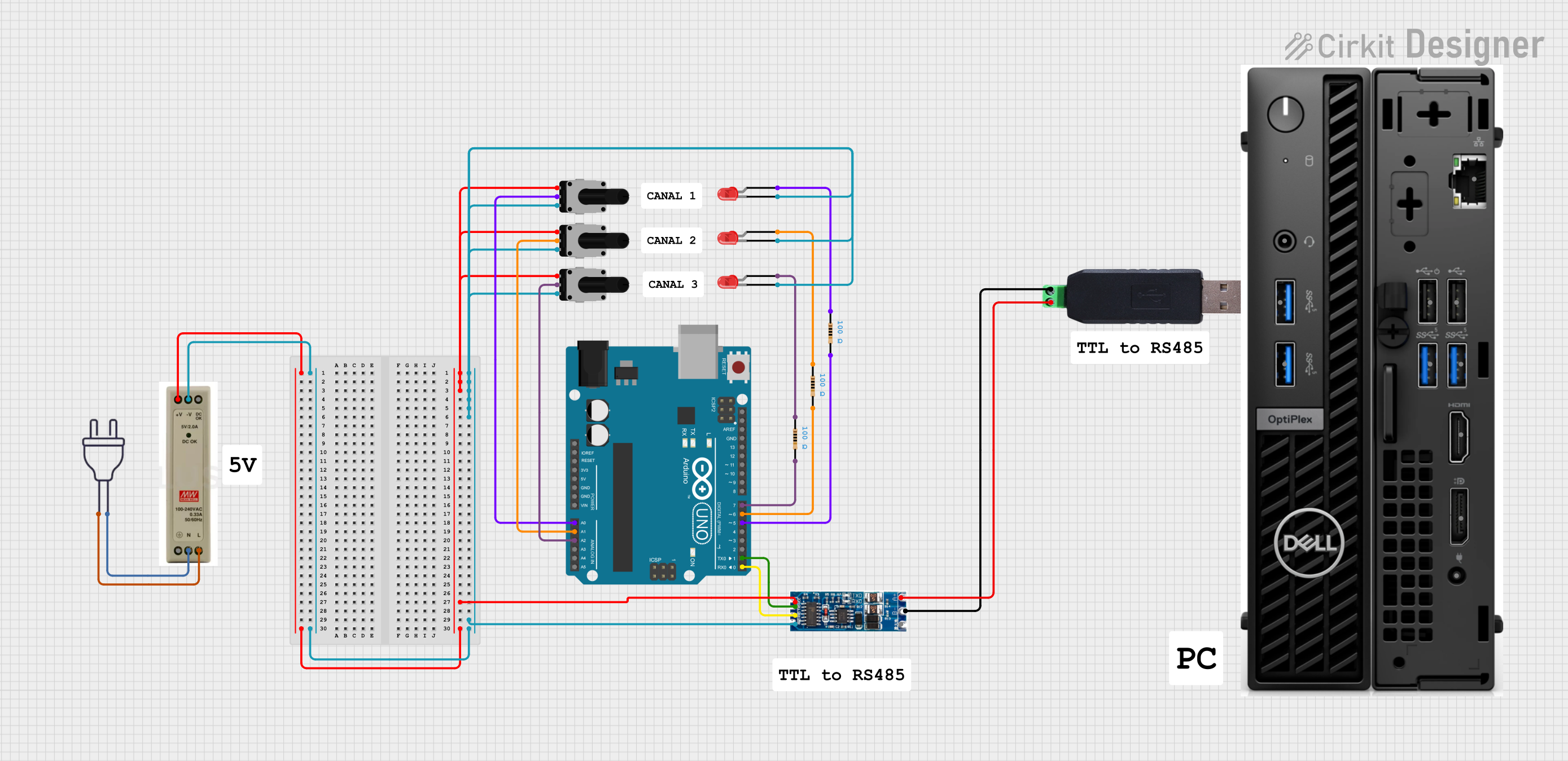
Example: Connecting RS485 to TTL with Arduino UNO
Below is an example of how to use the RS485 to TTL converter with an Arduino UNO to send and receive data.
Circuit Connections
- RS485 to TTL Module:
- VCC → 5V (Arduino)
- GND → GND (Arduino)
- RO → Pin 10 (Arduino RX)
- DI → Pin 11 (Arduino TX)
- DE → Pin 8 (Arduino GPIO)
- RE → Pin 8 (Arduino GPIO)
- A → RS485 Line A
- B → RS485 Line B
Arduino Code
#define DE_RE_PIN 8  // Pin to control DE and RE (combined control)
#define TX_PIN 11    // Arduino TX pin connected to DI
#define RX_PIN 10    // Arduino RX pin connected to RO

void setup() {
  pinMode(DE_RE_PIN, OUTPUT);  // Set DE/RE pin as output
  digitalWrite(DE_RE_PIN, LOW);  // Set to receive mode initially
  Serial.begin(9600);  // Initialize serial communication
  Serial.println("RS485 to TTL Communication Initialized");
}

void loop() {
  // Example: Sending data
  digitalWrite(DE_RE_PIN, HIGH);  // Enable transmission
  delay(10);  // Small delay to ensure mode switch
  Serial.println("Hello RS485!");  // Send data
  delay(10);  // Small delay to ensure data is sent
  digitalWrite(DE_RE_PIN, LOW);  // Enable reception

  // Example: Receiving data
  if (Serial.available()) {
    String receivedData = Serial.readString();  // Read incoming data
    Serial.print("Received: ");
    Serial.println(receivedData);
  }

  delay(1000);  // Wait before next iteration
}
Note: Adjust the baud rate in the code to match your RS485 network's baud rate.
Troubleshooting and FAQs
Common Issues and Solutions
No Data Transmission or Reception:
- Verify the power supply voltage (VCC) and ground (GND) connections.
- Check the DE and RE pin states (ensure proper mode switching).
- Confirm the A and B lines are correctly connected to the RS485 bus.
Corrupted Data:
- Ensure all devices on the RS485 bus use the same baud rate.
- Add or verify the presence of termination resistors at both ends of the RS485 bus.
- Use shielded or twisted-pair cables to reduce noise.
Module Overheating:
- Check for short circuits on the RS485 lines.
- Ensure the module is not exposed to voltages beyond its rated limits.
Intermittent Communication:
- Verify the pull-up and pull-down resistors on the RS485 bus.
- Inspect the cable connections for loose or damaged wires.
FAQs
Q: Can I use the RS485 to TTL converter with a 3.3V microcontroller?
A: Yes, as long as the module supports 3.3V operation. Check the module's specifications before use.
Q: How many devices can I connect to an RS485 bus?
A: RS485 supports up to 32 devices on a single bus. For more devices, use repeaters.
Q: Do I need to manually toggle DE and RE for every transmission?
A: Yes, unless your module combines DE and RE into a single control pin. In that case, toggle the combined pin.
Q: Can I use the RS485 to TTL converter for half-duplex communication?
A: Yes, RS485 is inherently half-duplex. Use DE and RE to control the transmission and reception modes.
By following this documentation, you can effectively integrate the RS485 to TTL converter into your projects for reliable and efficient communication.