How to Use Adafruit PWM Servo Featherwing: Examples, Pinouts, and Specs
Introduction
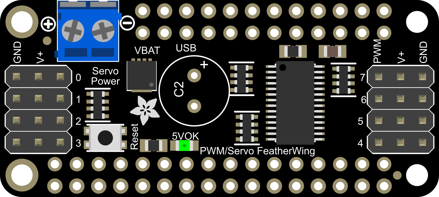
The Adafruit PWM Servo FeatherWing is an add-on board designed for use with the Feather ecosystem of development boards. It utilizes the PCA9685 PWM driver to control up to 8 servos, making it an ideal choice for robotics, animatronics, and any project requiring precise motion control. The board's ability to drive multiple servos with a single I2C interface simplifies wiring and conserves valuable GPIO pins on the Feather host board.
Explore Projects Built with Adafruit PWM Servo Featherwing
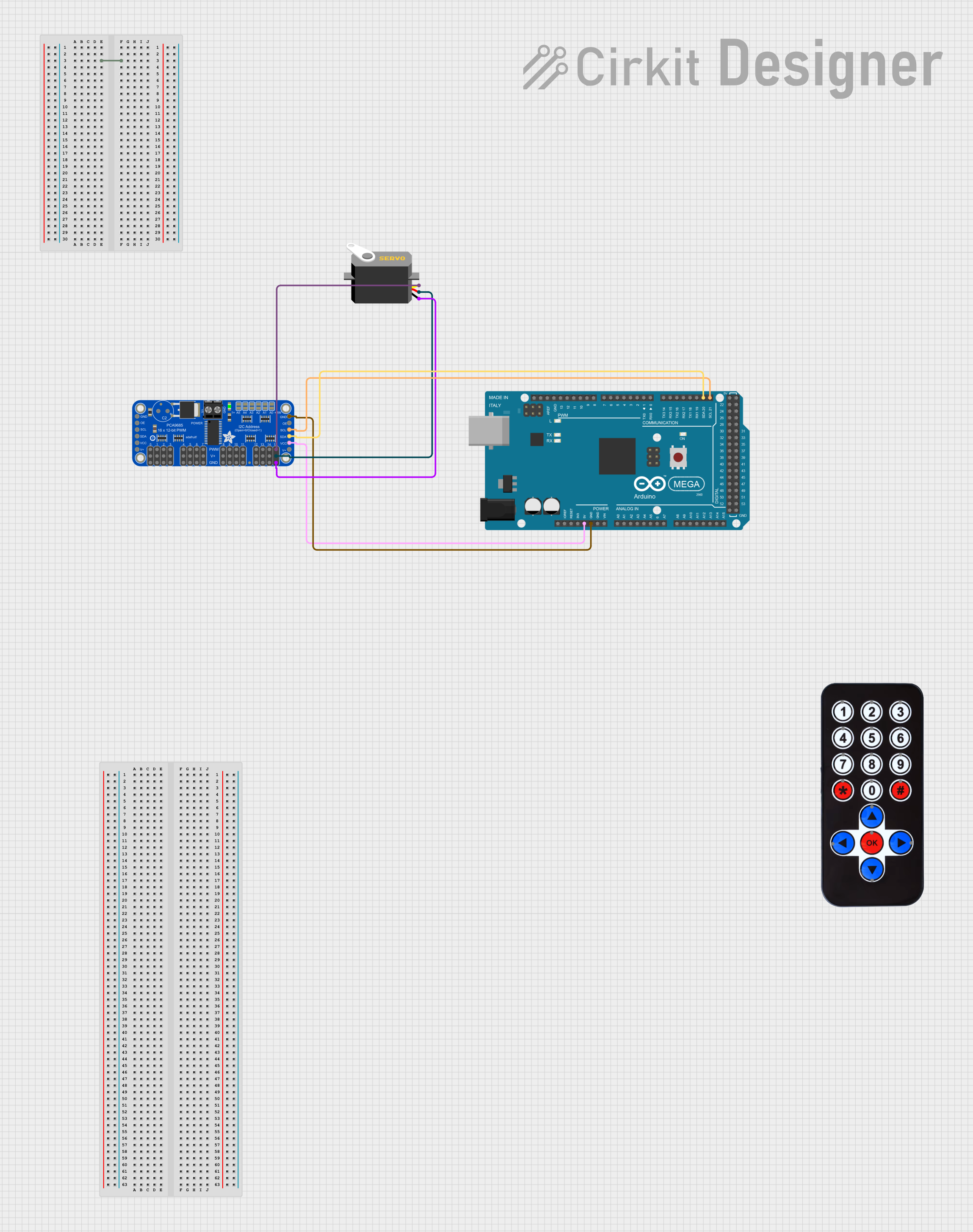
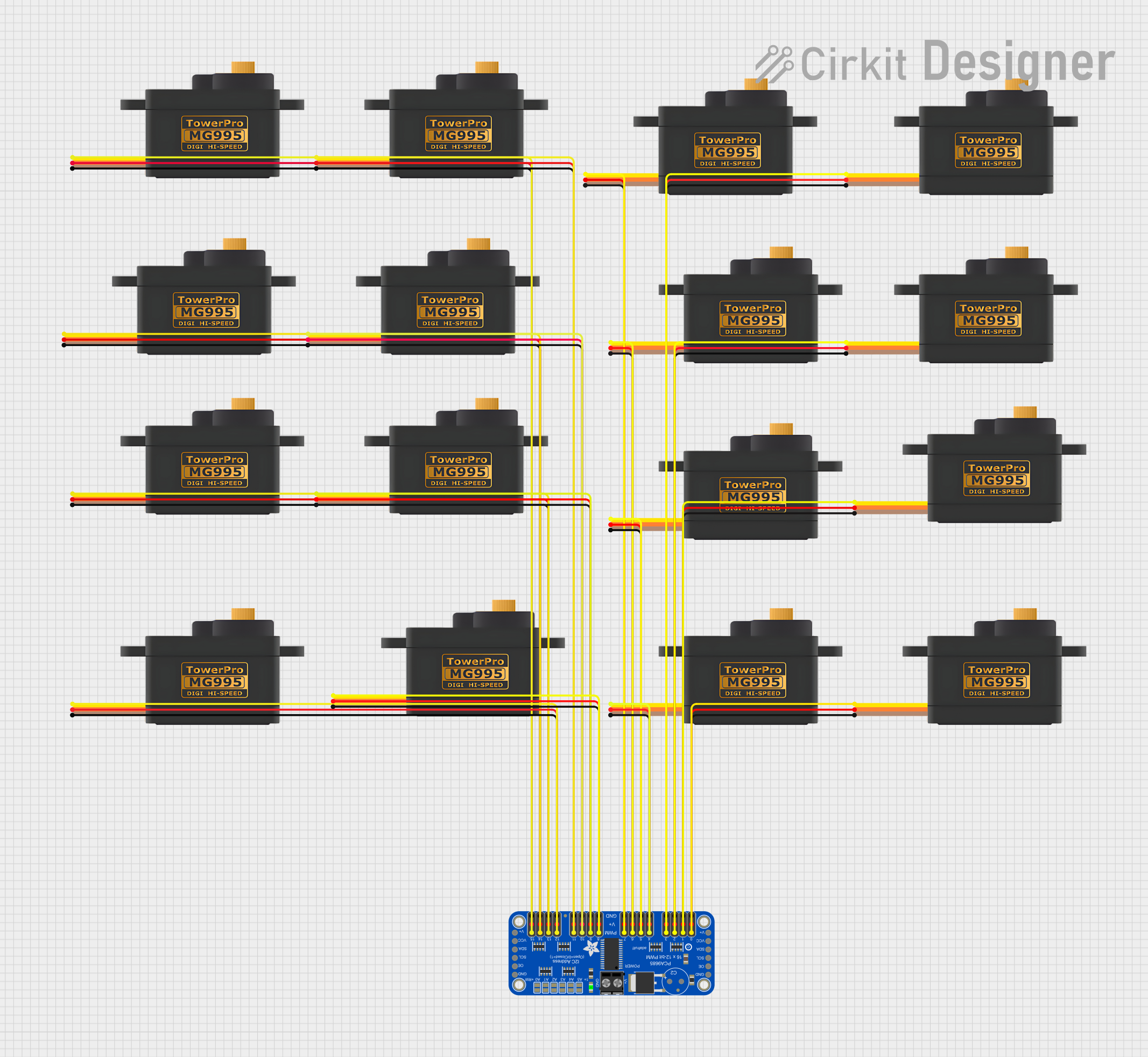
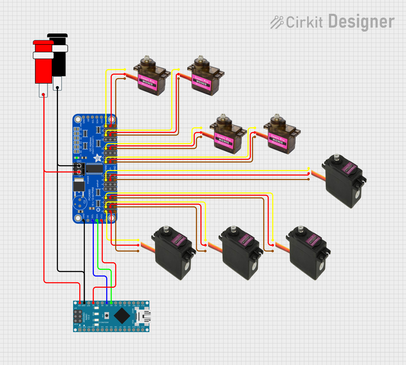
Explore Projects Built with Adafruit PWM Servo Featherwing
Common Applications and Use Cases
- Robotics arms and legs
- Animatronic figures
- Automated art installations
- Remote-controlled vehicles
- Prototyping and educational projects
Technical Specifications
Key Technical Details
- Voltage: 3V to 5V logic and power
- Current: 6mA (typical) when not driving servos
- Output Channels: 8 PWM outputs
- Frequency: 40Hz to 1000Hz adjustable PWM frequency
- Resolution: 12-bit resolution for each channel
Pin Configuration and Descriptions
| Pin Number | Function | Description |
|---|---|---|
| 1 | GND | Ground |
| 2 | V+ | Servo power supply (5V-6V recommended) |
| 3-10 | PWM 0 to PWM 7 | PWM output to control servo position |
| 11 | SCL | I2C clock line |
| 12 | SDA | I2C data line |
| 13 | ADDR | Address selection for I2C (solder jumper) |
| 14 | IRQ | Interrupt request (not used in most applications) |
Usage Instructions
How to Use the Component in a Circuit
Powering the Board:
- Connect a 5V-6V power supply to the V+ and GND pins to power the servos.
- Ensure the Feather board is powered separately as per its requirements.
Connecting Servos:
- Attach the servo's power cable to the V+ and GND pins.
- Connect the servo's control wire to one of the PWM output pins (PWM 0 to PWM 7).
I2C Communication:
- Connect the SCL and SDA pins to the corresponding I2C pins on the Feather board.
- If using multiple FeatherWings, set unique I2C addresses using the ADDR pin.
Important Considerations and Best Practices
- Do not exceed the recommended voltage for the servos to prevent damage.
- Ensure that the power supply can handle the current draw of all connected servos.
- Use external power when driving multiple or high-power servos to avoid overloading the Feather board's voltage regulator.
- Always disconnect power before making or changing connections.
Example Code for Arduino UNO
#include <Wire.h>
#include <Adafruit_PWMServoDriver.h>

// Initialize the PCA9685 using the default address (0x40).
Adafruit_PWMServoDriver pwm = Adafruit_PWMServoDriver();

void setup() {
  Serial.begin(9600);
  Serial.println("8-channel PWM test!");

  pwm.begin();
  pwm.setPWMFreq(60);  // Set frequency to 60 Hz
}

void loop() {
  // Sweep each servo back and forth
  for (uint16_t pulselen = SERVOMIN; pulselen < SERVOMAX; pulselen++) {
    pwm.setPWM(0, 0, pulselen);
  }

  delay(500);
  for (uint16_t pulselen = SERVOMAX; pulselen > SERVOMIN; pulselen--) {
    pwm.setPWM(0, 0, pulselen);
  }

  delay(500);
}

// Depending on your servo make, the pulse width min and max may vary
#define SERVOMIN  150 // This is the 'minimum' pulse length count (out of 4096)
#define SERVOMAX  600 // This is the 'maximum' pulse length count (out of 4096)
Troubleshooting and FAQs
Common Issues
- Servos not responding: Check power connections and ensure the power supply is adequate.
- Jittery servo movement: This can be due to a low-quality power supply or interference on the I2C line.
- I2C communication errors: Ensure there are no address conflicts and that the SDA/SCL lines are connected properly.
Solutions and Tips for Troubleshooting
- Use a multimeter to verify power supply voltage and servo connections.
- If using long wires for I2C communication, add pull-up resistors to reduce interference.
- Check and re-solder any loose connections or cold solder joints.
FAQs
Q: Can I control more than 8 servos with this board? A: Yes, by stacking multiple FeatherWings and setting unique I2C addresses, you can control additional servos.
Q: What is the maximum number of boards I can stack? A: You can stack up to 62 boards for a total of 496 servos, limited by the number of available I2C addresses.
Q: Can I use this board with other microcontrollers besides the Feather? A: Yes, as long as the microcontroller supports I2C communication and operates at 3V to 5V logic levels.
Q: Do I need to install any libraries to use this board with an Arduino?
A: Yes, you will need to install the Adafruit_PWMServoDriver library available through the Arduino Library Manager.