
How to Use IC PWR SWITCH N-CHAN 1:1 18DIP: Examples, Pinouts, and Specs
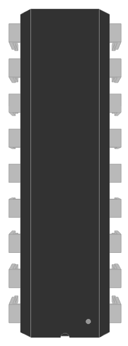
 Design with IC PWR SWITCH N-CHAN 1:1 18DIP in Cirkit Designer
Introduction
The TBD62083APG is an integrated circuit (IC) power switch manufactured by Toshiba Semiconductor and Storage. It features an N-channel MOSFET configuration, designed for efficient power management in electronic circuits. This IC is housed in an 18-pin dual in-line package (DIP), making it suitable for a wide range of applications.
Explore Projects Built with IC PWR SWITCH N-CHAN 1:1 18DIP
 Open Project in Cirkit Designer
 Open Project in Cirkit Designer
 Open Project in Cirkit Designer
 Open Project in Cirkit Designer
Explore Projects Built with IC PWR SWITCH N-CHAN 1:1 18DIP
Open Project in Cirkit DesignerOpen Project in Cirkit DesignerOpen Project in Cirkit DesignerOpen Project in Cirkit DesignerCommon Applications and Use Cases
- Motor control in robotics and industrial automation
- LED and lighting control systems
- Power distribution in embedded systems
- High-current switching in consumer electronics
- Relay driving in automotive and industrial applications
Technical Specifications
Key Technical Details
| Parameter | Value |
|---|---|
| Manufacturer | Toshiba Semiconductor and Storage |
| Part Number | TBD62083APG |
| Configuration | N-channel MOSFET |
| Package Type | 18-pin DIP |
| Operating Voltage Range | 4.5V to 30V |
| Maximum Output Current | 500mA per channel |
| Number of Channels | 8 |
| Input Voltage (High) | 2.7V (minimum) |
| Input Voltage (Low) | 0.8V (maximum) |
| Power Dissipation | 1.47W (at 25°C) |
| Operating Temperature | -40°C to +85°C |
Pin Configuration and Descriptions
The TBD62083APG has 18 pins, with the following configuration:
| Pin Number | Pin Name | Description |
|---|---|---|
| 1-8 | IN1-IN8 | Input pins for channels 1 to 8 |
| 9 | GND | Ground pin |
| 10-17 | OUT1-OUT8 | Output pins for channels 1 to 8 |
| 18 | VCC | Supply voltage pin (4.5V to 30V) |
Usage Instructions
How to Use the Component in a Circuit
- Power Supply: Connect the VCC pin (Pin 18) to a stable power source within the operating voltage range (4.5V to 30V). Connect the GND pin (Pin 9) to the circuit ground.
- Inputs: Apply control signals to the input pins (IN1-IN8). A HIGH signal (≥2.7V) will turn on the corresponding N-channel MOSFET, allowing current to flow through the respective output pin (OUT1-OUT8).
- Outputs: Connect the load (e.g., motor, LED, relay) to the output pins (OUT1-OUT8). Ensure the load current does not exceed 500mA per channel.
- Decoupling Capacitor: Place a decoupling capacitor (e.g., 0.1µF) near the VCC pin to stabilize the power supply and reduce noise.
Important Considerations and Best Practices
- Thermal Management: Ensure adequate heat dissipation, especially when driving multiple high-current loads. Use a heatsink or proper ventilation if necessary.
- Input Signal Levels: Verify that the input signals meet the required voltage thresholds (HIGH ≥ 2.7V, LOW ≤ 0.8V).
- Load Protection: Add flyback diodes across inductive loads (e.g., motors, relays) to protect the IC from voltage spikes.
- Unused Channels: If any channels are unused, leave their input pins unconnected or tied to GND to avoid accidental activation.
Example: Using TBD62083APG with Arduino UNO
Below is an example of controlling an LED using the TBD62083APG and an Arduino UNO:
// Define the input pin connected to the TBD62083APG
const int controlPin = 7; // Arduino pin connected to IN1 of the IC

void setup() {
  pinMode(controlPin, OUTPUT); // Set the control pin as an output
}

void loop() {
  digitalWrite(controlPin, HIGH); // Turn on the LED
  delay(1000); // Wait for 1 second
  digitalWrite(controlPin, LOW); // Turn off the LED
  delay(1000); // Wait for 1 second
}
Note: Connect the Arduino's control pin to the IN1 pin of the TBD62083APG. The corresponding OUT1 pin should be connected to the LED (with a current-limiting resistor).
Troubleshooting and FAQs
Common Issues and Solutions
No Output Signal:
- Verify that the VCC and GND pins are properly connected.
- Check the input signal levels. Ensure they meet the required HIGH and LOW thresholds.
- Confirm that the load is correctly connected to the output pin.
Overheating:
- Ensure the load current does not exceed 500mA per channel.
- Use proper thermal management techniques, such as heatsinks or forced air cooling.
Load Not Turning Off:
- Check for any short circuits between the output pin and the power supply.
- Ensure the input signal is correctly set to LOW (≤0.8V).
Noise or Instability:
- Add a decoupling capacitor near the VCC pin to stabilize the power supply.
- Use shielded cables for input signals to reduce electromagnetic interference.
FAQs
Q1: Can I use the TBD62083APG to drive a DC motor?
Yes, the TBD62083APG can drive DC motors, provided the motor's current does not exceed 500mA per channel. For higher currents, consider using multiple channels in parallel.
Q2: What happens if I exceed the maximum output current?
Exceeding the maximum output current can damage the IC. Always ensure the load current is within the specified limits.
Q3: Can I use this IC with a 3.3V microcontroller?
Yes, the TBD62083APG is compatible with 3.3V logic levels, as the minimum HIGH input voltage is 2.7V.
Q4: Do I need external resistors for the input pins?
No, the TBD62083APG has internal pull-down resistors on the input pins. However, you can add external resistors if additional noise immunity is required.