Cirkit Designer Logo
Cirkit Designer
Your all-in-one circuit design IDE
Home / 
Component Documentation

How to Use 12V SINGLE CHANNEL RELAY: Examples, Pinouts, and Specs

Image of 12V SINGLE CHANNEL RELAY
Cirkit Designer LogoDesign with 12V SINGLE CHANNEL RELAY in Cirkit Designer

Introduction

A 12V single channel relay is an electromechanical switch that allows you to control a high power device using a low power signal. It acts as a bridge between a control circuit (operating at low voltage) and a load circuit (operating at high voltage). This component is widely used in automation systems, home appliances, and automotive electronics where it is necessary to control devices such as motors, lights, and other high power loads.

Explore Projects Built with 12V SINGLE CHANNEL RELAY

Use Cirkit Designer to design, explore, and prototype these projects online. Some projects support real-time simulation. Click "Open Project" to start designing instantly!
Battery-Powered 4-Channel Relay Control with LED Indicators
Image of RELLAY BOARD TEST: A project utilizing 12V SINGLE CHANNEL RELAY in a practical application
This circuit consists of a 5V battery powering a 4-channel relay module, which controls four LEDs (red, yellow, green, and blue) through individual resistors. Each relay channel is activated by a corresponding SPST toggle switch, allowing manual control of the LEDs.
Cirkit Designer LogoOpen Project in Cirkit Designer
Arduino Mega 2560 Controlled 12V Blue LED with Relay and LabVIEW Integration
Image of Led control with arduino: A project utilizing 12V SINGLE CHANNEL RELAY in a practical application
This circuit uses a Mega 2560 R3 microcontroller to control a 12V Blue LED via a single-channel relay. The relay is powered by a 12V power supply and is controlled through pin D7 of the microcontroller, which toggles the LED on and off based on the microcontroller's output.
Cirkit Designer LogoOpen Project in Cirkit Designer
ESP8266 NodeMCU Controlled AC Light with Relay
Image of Home Automation with whatsapp: A project utilizing 12V SINGLE CHANNEL RELAY in a practical application
This circuit uses an ESP8266 NodeMCU microcontroller to control a 12V single-channel relay, which in turn switches an AC-powered red light on and off. The relay's control input (IN) is connected to a digital output (D1) on the ESP8266, allowing the microcontroller to activate the relay. The relay's normally open (NO) contact is used to complete the circuit for the red light when the relay is energized, and the power for the relay's coil and the microcontroller is supplied by a 5V DC source.
Cirkit Designer LogoOpen Project in Cirkit Designer
Arduino-Controlled IR Relay Switching System
Image of CONTROLING APPLIANCES WITH IR RECIEVER: A project utilizing 12V SINGLE CHANNEL RELAY in a practical application
This circuit consists of an Arduino UNO microcontroller interfaced with three 12V single-channel relays and an IR receiver. The Arduino controls the relays via digital pins D8, D9, and D10, allowing it to switch external circuits connected to the relays. The IR receiver is connected to the Arduino's digital pin D7 and is powered by the 3.3V pin, enabling the Arduino to receive infrared signals for potential remote control applications.
Cirkit Designer LogoOpen Project in Cirkit Designer

Explore Projects Built with 12V SINGLE CHANNEL RELAY

Use Cirkit Designer to design, explore, and prototype these projects online. Some projects support real-time simulation. Click "Open Project" to start designing instantly!
Image of RELLAY BOARD TEST: A project utilizing 12V SINGLE CHANNEL RELAY in a practical application
Battery-Powered 4-Channel Relay Control with LED Indicators
This circuit consists of a 5V battery powering a 4-channel relay module, which controls four LEDs (red, yellow, green, and blue) through individual resistors. Each relay channel is activated by a corresponding SPST toggle switch, allowing manual control of the LEDs.
Cirkit Designer LogoOpen Project in Cirkit Designer
Image of Led control with arduino: A project utilizing 12V SINGLE CHANNEL RELAY in a practical application
Arduino Mega 2560 Controlled 12V Blue LED with Relay and LabVIEW Integration
This circuit uses a Mega 2560 R3 microcontroller to control a 12V Blue LED via a single-channel relay. The relay is powered by a 12V power supply and is controlled through pin D7 of the microcontroller, which toggles the LED on and off based on the microcontroller's output.
Cirkit Designer LogoOpen Project in Cirkit Designer
Image of Home Automation with whatsapp: A project utilizing 12V SINGLE CHANNEL RELAY in a practical application
ESP8266 NodeMCU Controlled AC Light with Relay
This circuit uses an ESP8266 NodeMCU microcontroller to control a 12V single-channel relay, which in turn switches an AC-powered red light on and off. The relay's control input (IN) is connected to a digital output (D1) on the ESP8266, allowing the microcontroller to activate the relay. The relay's normally open (NO) contact is used to complete the circuit for the red light when the relay is energized, and the power for the relay's coil and the microcontroller is supplied by a 5V DC source.
Cirkit Designer LogoOpen Project in Cirkit Designer
Image of CONTROLING APPLIANCES WITH IR RECIEVER: A project utilizing 12V SINGLE CHANNEL RELAY in a practical application
Arduino-Controlled IR Relay Switching System
This circuit consists of an Arduino UNO microcontroller interfaced with three 12V single-channel relays and an IR receiver. The Arduino controls the relays via digital pins D8, D9, and D10, allowing it to switch external circuits connected to the relays. The IR receiver is connected to the Arduino's digital pin D7 and is powered by the 3.3V pin, enabling the Arduino to receive infrared signals for potential remote control applications.
Cirkit Designer LogoOpen Project in Cirkit Designer

Common Applications and Use Cases

  • Home automation (e.g., turning lights on/off)
  • Automotive electronics (e.g., starting an engine)
  • Industrial controls (e.g., machinery operation)
  • Robotics (e.g., actuator control)

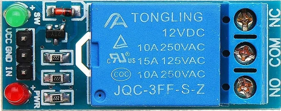
Technical Specifications

Key Technical Details

  • Operating Voltage (Coil): 12V DC
  • Switching Voltage: Up to 250V AC or 30V DC
  • Current Rating: Typically 10A
  • Contact Type: SPDT (Single Pole Double Throw)
  • Control Signal: TTL compatible (5V)

Pin Configuration and Descriptions

Pin Number Description Notes
1 VCC Connect to 12V power supply
2 GND Connect to ground
3 IN Control signal input (TTL level)
4 Normally Closed (NC) Load connected, active when relay is off
5 Common (COM) Connect to load power supply
6 Normally Open (NO) Load connected, active when relay is on
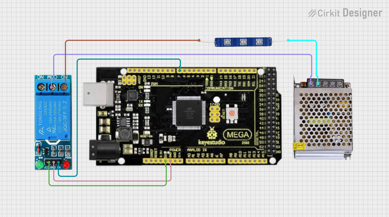
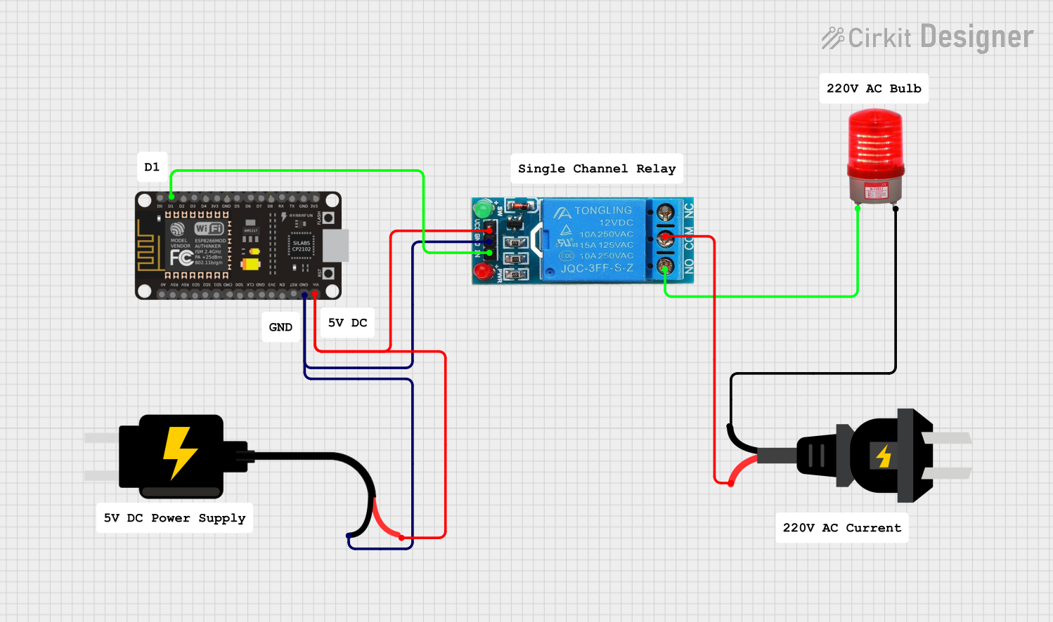
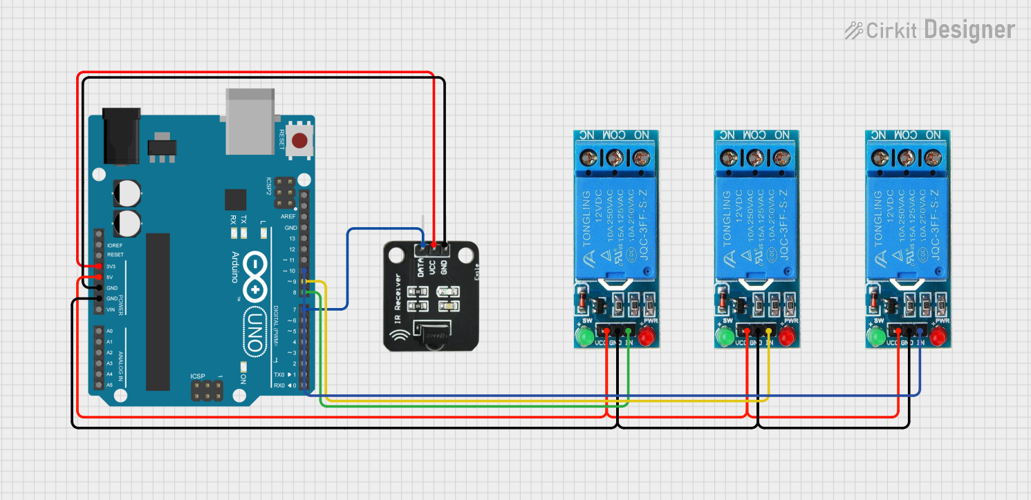
Usage Instructions

How to Use the Component in a Circuit

  1. Power Supply Connection: Connect the VCC pin to a 12V power supply and the GND pin to the ground.
  2. Control Signal: Apply a TTL level signal (5V) to the IN pin to activate the relay.
  3. Load Connection: Connect the load you wish to control to the COM pin and choose either NO or NC pin depending on whether you want the load to be powered when the relay is activated (NO) or when it is not (NC).

Important Considerations and Best Practices

  • Ensure that the power supply voltage matches the relay coil voltage (12V).
  • Do not exceed the maximum switching voltage and current ratings of the relay.
  • Use a flyback diode across the relay coil to prevent back EMF when the relay is turned off.
  • If the relay is being driven by a microcontroller, use a transistor to amplify the control signal if necessary.
  • Always ensure proper isolation between the control circuit and the high power load circuit for safety.

Example Code for Arduino UNO

// Define the relay control pin
const int relayPin = 7;

void setup() {
  // Set the relay pin as an output
  pinMode(relayPin, OUTPUT);
}

void loop() {
  // Turn on the relay
  digitalWrite(relayPin, HIGH);
  delay(1000); // Wait for 1 second
  
  // Turn off the relay
  digitalWrite(relayPin, LOW);
  delay(1000); // Wait for 1 second
}

Troubleshooting and FAQs

Common Issues Users Might Face

  • Relay does not activate: Check the power supply and control signal connections.
  • Intermittent operation: Ensure that the control signal is stable and that there is no loose wiring.
  • Clicking sound but no action: Verify that the load does not exceed the relay's rated capacity.

Solutions and Tips for Troubleshooting

  • Double-check all connections, especially the power supply and ground.
  • Use a multimeter to verify the presence of the control signal.
  • Inspect the relay for any signs of damage or overheating.

FAQs

Q: Can I control this relay with a 5V signal? A: Yes, the control signal is TTL compatible, which means it can be operated with a 5V signal.

Q: What is the purpose of the NC and NO pins? A: The NC pin is connected to the load when the relay is off, and the NO pin is connected when the relay is on. This allows for normally closed or normally open operations.

Q: Can I use this relay with AC loads? A: Yes, the relay can switch AC loads up to 250V, but ensure that you are qualified to work with high voltage AC safely.

Q: How can I protect my microcontroller from the relay's back EMF? A: Use a flyback diode across the relay coil, and consider using a transistor between the microcontroller and the relay if necessary.