How to Use SSR-25DA 25A 250V Solid State Relay Module: Examples, Pinouts, and Specs
Introduction
The SSR-25DA is a solid state relay (SSR) manufactured by HiLetgo (Part ID: 3-01-1247-25A). This relay is designed to switch AC loads of up to 25A at 250V using a low-voltage DC control signal. Unlike traditional mechanical relays, the SSR-25DA uses semiconductor devices for switching, offering faster response times, silent operation, and a longer lifespan.
Explore Projects Built with SSR-25DA 25A 250V Solid State Relay Module


Explore Projects Built with SSR-25DA 25A 250V Solid State Relay Module
Common Applications
- Industrial automation and control systems
- Heating, ventilation, and air conditioning (HVAC) systems
- Motor control and lighting systems
- Home automation projects
- Arduino and microcontroller-based projects for controlling high-power AC devices
Technical Specifications
Key Specifications
| Parameter | Value |
|---|---|
| Manufacturer | HiLetgo |
| Part ID | 3-01-1247-25A |
| Load Voltage Range | 24V AC to 250V AC |
| Load Current Rating | 25A |
| Control Voltage Range | 3V DC to 32V DC |
| Control Current | ≤ 25mA |
| Trigger Voltage (ON) | ≥ 3V DC |
| Trigger Voltage (OFF) | ≤ 1V DC |
| Isolation Voltage | 2500V AC |
| Switching Type | Zero-crossing |
| Operating Temperature | -30°C to +75°C |
| Dimensions | 58mm x 45mm x 23mm |
| Weight | ~110g |
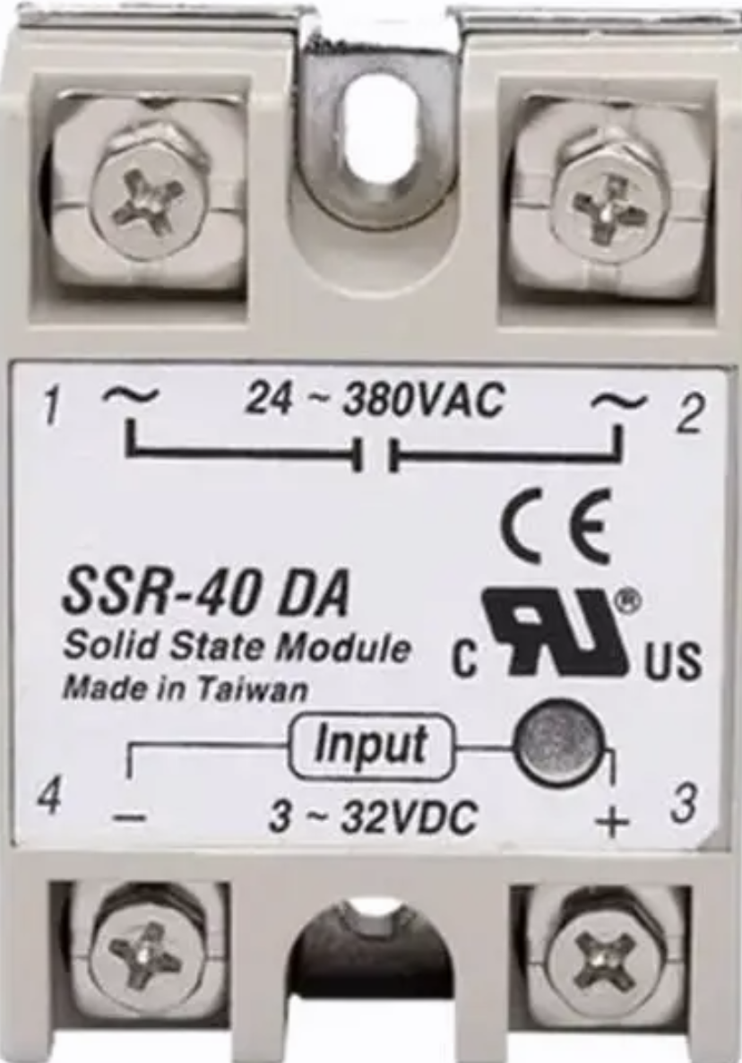
Pin Configuration and Descriptions
The SSR-25DA has four terminals, divided into two sections: the control side and the load side.
Control Side (Input Terminals)
| Pin | Label | Description |
|---|---|---|
| 1 | + | Positive DC control signal (3V to 32V DC) |
| 2 | - | Negative DC control signal (ground) |
Load Side (Output Terminals)
| Pin | Label | Description |
|---|---|---|
| 3 | ~ | AC load terminal 1 (connect to AC load) |
| 4 | ~ | AC load terminal 2 (connect to AC load) |
Usage Instructions
How to Use the SSR-25DA in a Circuit
Control Side Connection:
- Connect the positive control signal (e.g., from a microcontroller or Arduino) to the
+terminal. - Connect the ground of the control signal to the
-terminal. - Ensure the control voltage is within the range of 3V to 32V DC.
- Connect the positive control signal (e.g., from a microcontroller or Arduino) to the
Load Side Connection:
- Connect one terminal of the AC load to one of the
~terminals on the SSR. - Connect the other
~terminal to the AC power source. - Ensure the load does not exceed the maximum rating of 25A at 250V AC.
- Connect one terminal of the AC load to one of the
Powering the Circuit:
- When the control signal voltage is applied (≥ 3V DC), the SSR will switch ON, allowing current to flow through the load.
- When the control signal voltage is removed (≤ 1V DC), the SSR will switch OFF, stopping current flow.
Important Considerations and Best Practices
- Heat Dissipation: The SSR-25DA generates heat during operation. Use a heatsink or mount the relay on a metal surface to ensure proper heat dissipation, especially for high-current loads.
- Isolation: Ensure proper electrical isolation between the control and load sides to prevent damage to the control circuit.
- Zero-Crossing Switching: The SSR-25DA uses zero-crossing technology, which minimizes electrical noise and extends the lifespan of connected devices.
- Overcurrent Protection: Use a fuse or circuit breaker to protect the relay and load from overcurrent conditions.
- Avoid Inductive Loads: For inductive loads (e.g., motors), use a snubber circuit to suppress voltage spikes.
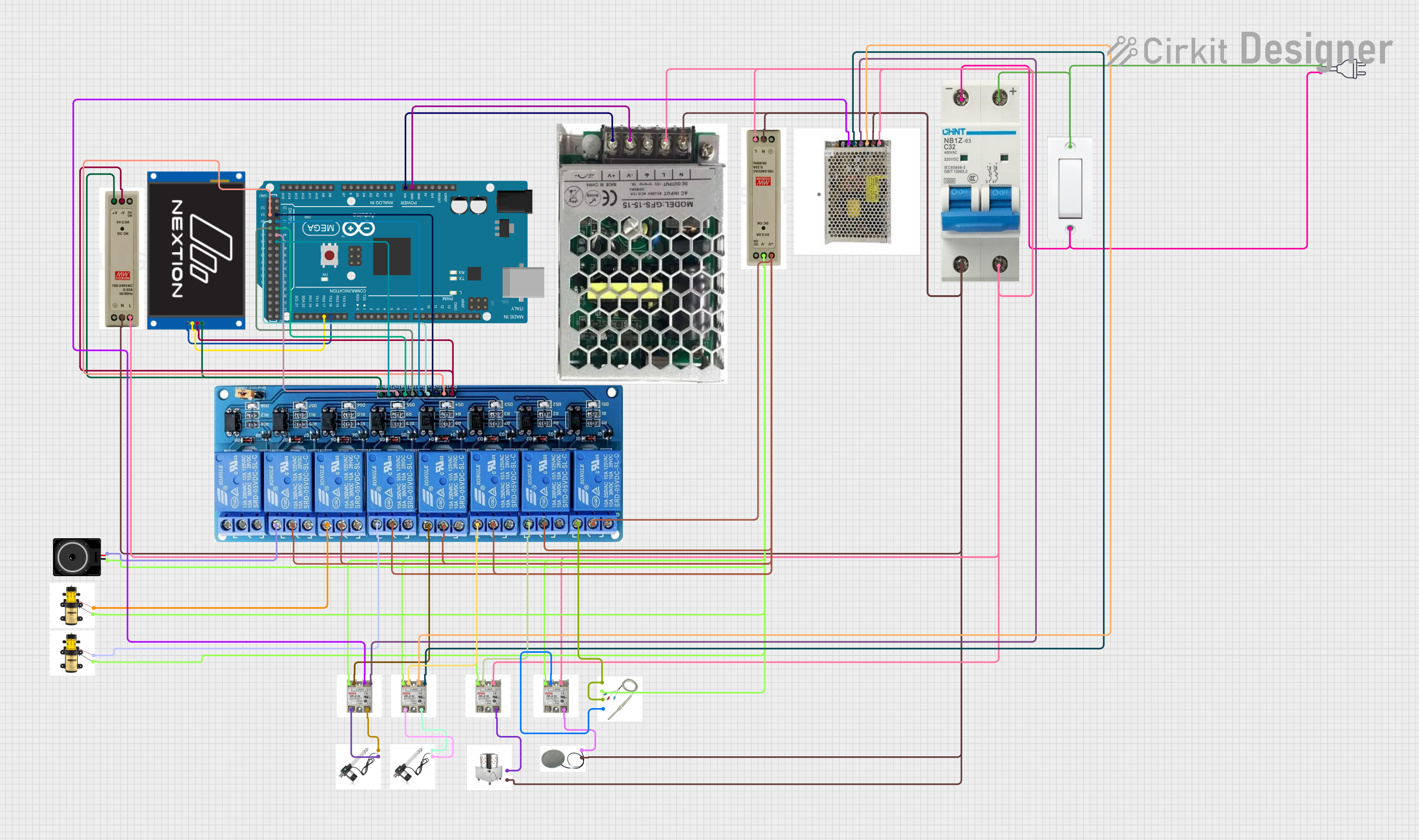
Example: Using SSR-25DA with Arduino UNO
Below is an example of how to control an AC light bulb using the SSR-25DA and an Arduino UNO.
Circuit Diagram
- Connect the Arduino's digital pin (e.g., pin 9) to the
+terminal of the SSR. - Connect the Arduino's GND to the
-terminal of the SSR. - Connect the AC light bulb to the load side of the SSR as described above.
Arduino Code
// Define the pin connected to the SSR control terminal
const int ssrPin = 9;

void setup() {
  pinMode(ssrPin, OUTPUT); // Set the SSR pin as an output
}

void loop() {
  digitalWrite(ssrPin, HIGH); // Turn ON the SSR (AC load ON)
  delay(5000);               // Keep the load ON for 5 seconds
  digitalWrite(ssrPin, LOW);  // Turn OFF the SSR (AC load OFF)
  delay(5000);               // Keep the load OFF for 5 seconds
}
Note: Ensure proper safety precautions when working with AC mains voltage. Disconnect power before making any connections.
Troubleshooting and FAQs
Common Issues and Solutions
| Issue | Possible Cause | Solution |
|---|---|---|
| SSR does not turn ON | Control voltage is too low | Ensure control voltage is ≥ 3V DC |
| SSR remains ON even without signal | Faulty SSR or incorrect wiring | Check wiring and replace the SSR if needed |
| Excessive heat during operation | High load current or poor heat dissipation | Use a heatsink or reduce load current |
| Load does not turn OFF | Inductive load causing voltage spikes | Add a snubber circuit across the load |
FAQs
Can the SSR-25DA be used with DC loads?
- No, the SSR-25DA is designed for AC loads only. For DC loads, use a DC-specific SSR.
What happens if the load exceeds 25A?
- Exceeding the rated current can damage the SSR. Always use a fuse or circuit breaker for protection.
Is the SSR-25DA suitable for dimming applications?
- No, the SSR-25DA is not designed for phase control or dimming. Use a dimmer-specific SSR for such applications.
Can I use the SSR-25DA without a heatsink?
- For low-current loads, a heatsink may not be necessary. However, for high-current loads, a heatsink is essential to prevent overheating.
By following this documentation, you can safely and effectively use the SSR-25DA in your projects.