Cirkit Designer LogoCirkit DesignerYour all-in-one circuit design IDE Launch Cirkit Designer App

How to Use TCRT 5000 IR SENSOR: Examples, Pinouts, and Specs

Image of TCRT 5000 IR SENSORDesign with TCRT 5000 IR SENSOR in Cirkit Designer

Introduction

The TCRT 5000 IR sensor is an infrared reflective sensor module that includes an infrared emitting diode and a phototransistor. It is designed to detect the presence of an object within a specific distance by reflecting infrared light off the object and measuring the intensity of the reflected light. This sensor is widely used in applications such as line following robots, object detection, and proximity sensing.

Explore Projects Built with TCRT 5000 IR SENSOR

Use Cirkit Designer to design, explore, and prototype these projects online. Some projects support real-time simulation. Click "Open Project" to start designing instantly!
Image of Raspberry Pi Zero-Based IR Sensor Array: A project utilizing TCRT 5000 IR SENSOR in a practical application

Raspberry Pi Zero-Based IR Sensor Array

This circuit integrates a Raspberry Pi Zero with two types of IR sensors: a TCRT 5000 IR sensor and a generic IR sensor. The Raspberry Pi Zero is configured to receive digital output signals from both sensors on GPIO14 and GPIO15 respectively, allowing it to process and respond to infrared light detection. The 5V and GND pins of the Raspberry Pi Zero provide power to both IR sensors, establishing a common voltage reference.

Open Project in Cirkit Designer
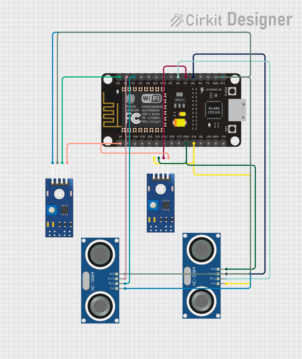
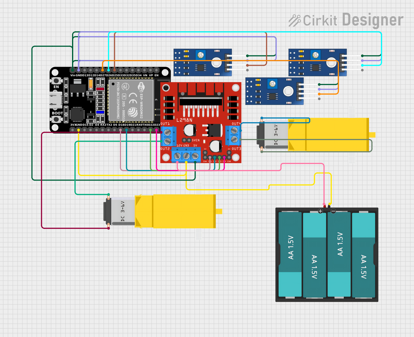
Image of ESP-8266 Based Obstacle Detection System with IR and Ultrasonic Sensors: A project utilizing TCRT 5000 IR SENSOR in a practical application
ESP-8266 Based Obstacle Detection System with IR and Ultrasonic Sensors

This circuit integrates two types of sensors, the TCRT 5000 IR sensors and HC-SR04 Ultrasonic sensors, with an ESP-8266 microcontroller. The IR sensors are connected to both analog and digital input pins on the ESP-8266, allowing for both threshold-based and precise distance measurements. The ultrasonic sensors are interfaced with digital pins for triggering and echo reception, enabling distance measurement through time-of-flight calculations. The ESP-8266 likely processes these sensor inputs for applications such as obstacle detection or proximity sensing, and could potentially communicate the data wirelessly given its capabilities.

Open Project in Cirkit Designer
Image of ESP32-Controlled Dual Gearmotor System with IR Sensing: A project utilizing TCRT 5000 IR SENSOR in a practical application
ESP32-Controlled Dual Gearmotor System with IR Sensing

This circuit features an ESP32 microcontroller interfaced with three TCRT 5000 IR sensors and two DC gearmotors controlled by an L298N motor driver. The ESP32 reads digital outputs from the IR sensors to likely make decisions based on line or obstacle detection, and it controls the gearmotors' directions and speeds, possibly for a robot or automated system. Power is supplied by a 6V battery connected to the motor driver, which also provides 5V to the ESP32 and the IR sensors.

Open Project in Cirkit Designer
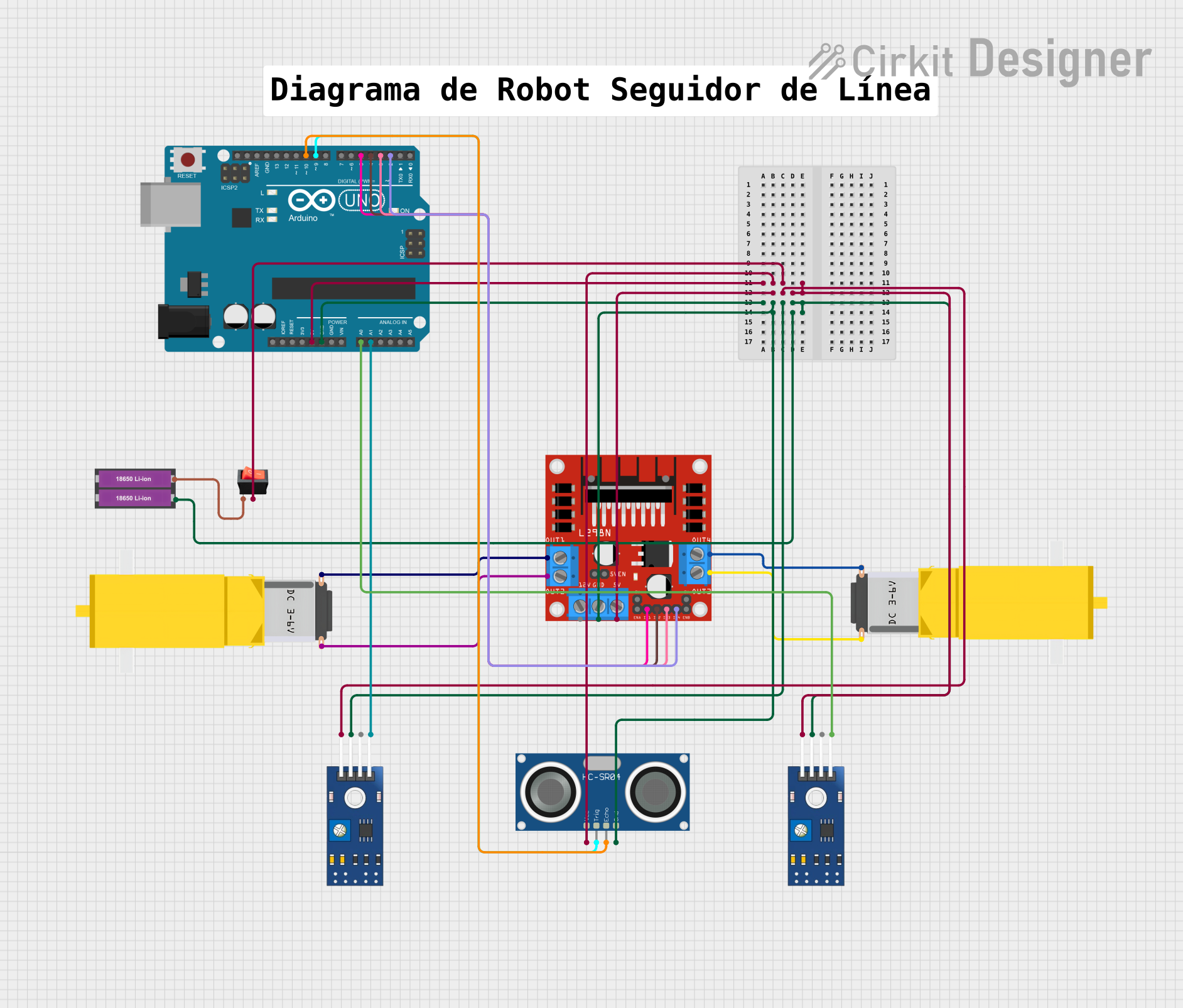
Image of Arduino-Controlled Obstacle-Avoiding Robot with IR and Ultrasonic Sensors: A project utilizing TCRT 5000 IR SENSOR in a practical application
Arduino-Controlled Obstacle-Avoiding Robot with IR and Ultrasonic Sensors

This circuit features an Arduino UNO microcontroller interfaced with two TCRT 5000 IR sensors, an HC-SR04 ultrasonic sensor, and an L298N DC motor driver controlling two gearmotors. The IR sensors and ultrasonic sensor are likely used for distance or obstacle detection, while the motor driver manages the direction and speed of the motors, possibly for a robot or automated vehicle. Power is supplied by a 18650 Li-ion battery pack, with a rocker switch to control power flow.

Open Project in Cirkit Designer

Common Applications and Use Cases

Technical Specifications

Key Technical Details

Pin Configuration and Descriptions

Pin Number Name Description
1 Vcc Power supply (3.3V to 5V)
2 GND Ground connection
3 OUT Digital output signal (active low)
4 EN Enable pin (optional use)
5 AO Analog output signal

Usage Instructions

How to Use the Component in a Circuit

  1. Power Supply: Connect the Vcc pin to a 3.3V or 5V power supply and the GND pin to the ground.
  2. Output Connection: Connect the OUT pin to a digital input pin on your microcontroller to read the digital signal. The AO pin can be connected to an analog input pin if you wish to read the analog signal.
  3. Enable Pin: The EN pin can be left unconnected if not used; otherwise, connect it to a digital output pin on your microcontroller to control the sensor's operation.

Important Considerations and Best Practices

Troubleshooting and FAQs

Common Issues Users Might Face

Solutions and Tips for Troubleshooting

Example Arduino Code

// Define the TCRT 5000 sensor output pin
const int sensorPin = 2;

void setup() {
  // Initialize the sensor output pin as an input
  pinMode(sensorPin, INPUT);
  // Begin serial communication at 9600 baud rate
  Serial.begin(9600);
}

void loop() {
  // Read the sensor value
  int sensorValue = digitalRead(sensorPin);
  // Print the sensor value to the Serial Monitor
  Serial.println(sensorValue);
  // Wait for 100 milliseconds before reading again
  delay(100);
}

Note: The above code assumes that the TCRT 5000 sensor's OUT pin is connected to digital pin 2 on the Arduino UNO. The code reads the digital output from the sensor and prints it to the Serial Monitor. If the sensor detects an object, it will print 0 (since the output is active low); otherwise, it will print 1.