How to Use Timer H3CR-A8: Examples, Pinouts, and Specs
Introduction
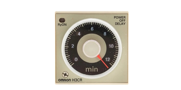
The Timer H3CR-A8 is a versatile time relay designed for controlling the timing of electrical circuits. Manufactured by Timer, this component offers multiple timing ranges and modes, making it ideal for precise control in a variety of applications. Its compact design, durability, and easy-to-read display make it a popular choice for industrial and commercial use.
Explore Projects Built with Timer H3CR-A8


Explore Projects Built with Timer H3CR-A8
Common Applications and Use Cases
- Industrial Automation: Used to control the timing of machinery and processes.
- Lighting Control: Enables timed switching of lighting systems.
- Motor Control: Provides delay or interval timing for motor operations.
- HVAC Systems: Used in heating, ventilation, and air conditioning systems for timed operations.
- Testing and Measurement: Ideal for applications requiring precise timing intervals.
Technical Specifications
The Timer H3CR-A8 is designed to meet the needs of a wide range of timing applications. Below are its key technical details:
General Specifications
| Parameter | Value |
|---|---|
| Manufacturer | Timer |
| Part Number | H3CR-A8 |
| Timing Ranges | 0.05 seconds to 300 hours (selectable) |
| Timing Modes | ON-delay, OFF-delay, Interval, One-shot |
| Operating Voltage | 100-240 VAC or 24-48 VDC (depending on model) |
| Power Consumption | Approx. 3 VA (AC) or 2 W (DC) |
| Contact Configuration | DPDT (Double Pole Double Throw) |
| Contact Rating | 5 A at 250 VAC (resistive load) |
| Ambient Operating Temp. | -10°C to +55°C |
| Mounting Style | Panel mounting or DIN rail mounting |
| Dimensions | 48 x 48 x 67 mm |
| Weight | Approx. 120 g |
Pin Configuration and Descriptions
The Timer H3CR-A8 features an 8-pin socket for easy connection. Below is the pin configuration:
| Pin Number | Description |
|---|---|
| 1 | Power Supply Input (AC/DC) |
| 2 | Power Supply Input (AC/DC) |
| 3 | Common Terminal for Output Relay |
| 4 | Normally Open (NO) Contact for Output Relay |
| 5 | Normally Closed (NC) Contact for Output Relay |
| 6 | Common Terminal for Second Output Relay (if applicable) |
| 7 | Normally Open (NO) Contact for Second Output Relay (if applicable) |
| 8 | Normally Closed (NC) Contact for Second Output Relay (if applicable) |
Usage Instructions
The Timer H3CR-A8 is straightforward to use, but proper setup is essential for optimal performance. Follow the steps below to integrate it into your circuit:
Step 1: Select the Timing Range and Mode
- Use the rotary switches on the front panel to select the desired timing range (e.g., seconds, minutes, hours).
- Set the timing mode (ON-delay, OFF-delay, Interval, or One-shot) using the mode selector.
Step 2: Wiring the Timer
- Connect the power supply to pins 1 and 2. Ensure the voltage matches the operating voltage of the timer.
- Wire the load to the output relay terminals (pins 3, 4, and 5 for the first relay; pins 6, 7, and 8 for the second relay, if applicable).
- Double-check all connections to ensure they are secure and correct.
Step 3: Adjust the Time Setting
- Use the time adjustment knob to set the desired delay or interval time.
- Verify the setting by observing the timer's display or indicator lights.
Step 4: Test the Timer
- Power on the circuit and observe the timer's operation.
- Ensure the relay switches as expected based on the selected timing mode and range.
Important Considerations and Best Practices
- Always verify the power supply voltage before connecting the timer to avoid damage.
- Use appropriate fuses or circuit breakers to protect the timer and connected devices.
- Avoid exposing the timer to excessive vibration, moisture, or extreme temperatures.
- For applications requiring high precision, periodically calibrate the timer.
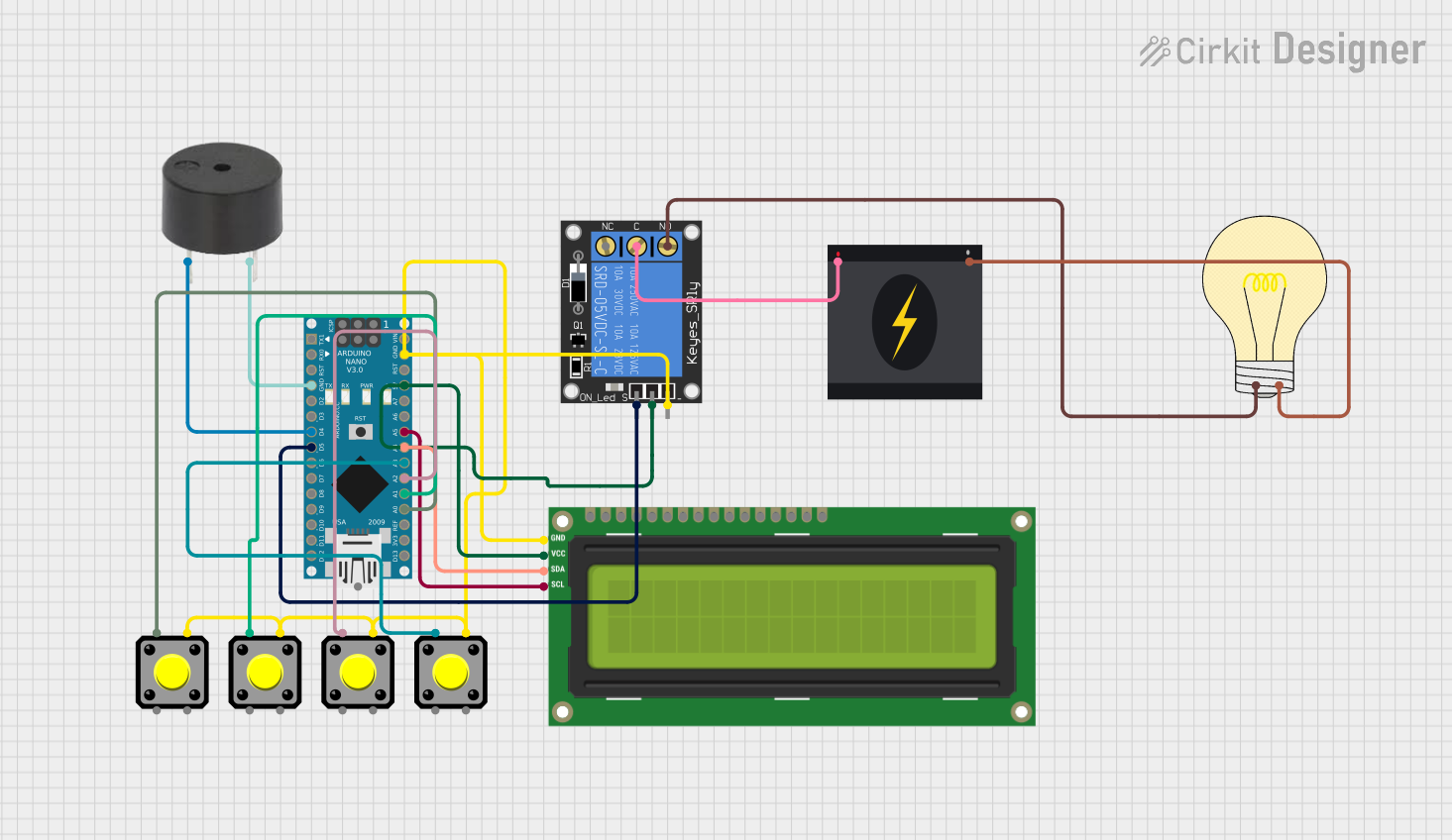
Example: Using Timer H3CR-A8 with an Arduino UNO
The Timer H3CR-A8 can be used in conjunction with an Arduino UNO for automation tasks. Below is an example of how to trigger the timer using a digital output pin:
// Example: Triggering Timer H3CR-A8 with Arduino UNO
const int timerTriggerPin = 7; // Pin connected to Timer H3CR-A8 input

void setup() {
  pinMode(timerTriggerPin, OUTPUT); // Set the pin as an output
}

void loop() {
  digitalWrite(timerTriggerPin, HIGH); // Activate the timer
  delay(5000); // Keep the timer active for 5 seconds
  digitalWrite(timerTriggerPin, LOW); // Deactivate the timer
  delay(10000); // Wait for 10 seconds before reactivating
}
Note: Ensure the Arduino's output voltage matches the input requirements of the Timer H3CR-A8.
Troubleshooting and FAQs
Common Issues and Solutions
| Issue | Possible Cause | Solution |
|---|---|---|
| Timer does not power on | Incorrect power supply voltage | Verify the power supply voltage and ensure it matches the timer's rating. |
| Relay does not activate | Incorrect wiring or timing mode | Check the wiring and ensure the correct timing mode is selected. |
| Timer operates intermittently | Loose connections or unstable power supply | Inspect all connections and ensure a stable power source is used. |
| Timing is inaccurate | Incorrect time range or knob setting | Verify the time range and adjust the time setting knob as needed. |
| Timer overheats | Overloaded relay contacts | Ensure the load does not exceed the relay's contact rating. |
Frequently Asked Questions
Can the Timer H3CR-A8 be used with DC power?
- Yes, the timer supports 24-48 VDC models. Ensure you select the correct model for your application.
What is the maximum load the relay can handle?
- The relay can handle up to 5 A at 250 VAC for resistive loads.
How do I reset the timer?
- The timer resets automatically after completing its cycle. For manual reset, power off the timer and restart it.
Can I use the timer outdoors?
- The Timer H3CR-A8 is not designed for outdoor use unless housed in a weatherproof enclosure.
By following this documentation, you can effectively integrate and troubleshoot the Timer H3CR-A8 in your projects.