How to Use Analog to Digital Converter (DAC): Examples, Pinouts, and Specs
Introduction
An Analog to Digital Converter (ADC) is an essential electronic component that converts analog signals, such as voltage or current, into digital data. This conversion enables microcontrollers, processors, and other digital systems to process and manipulate real-world signals, such as temperature, sound, or light, in a digital format.
Explore Projects Built with Analog to Digital Converter (DAC)
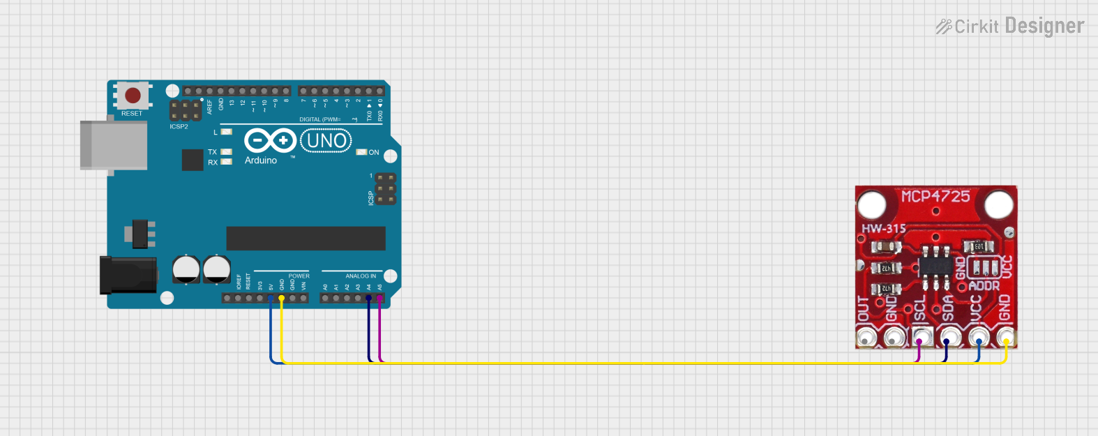
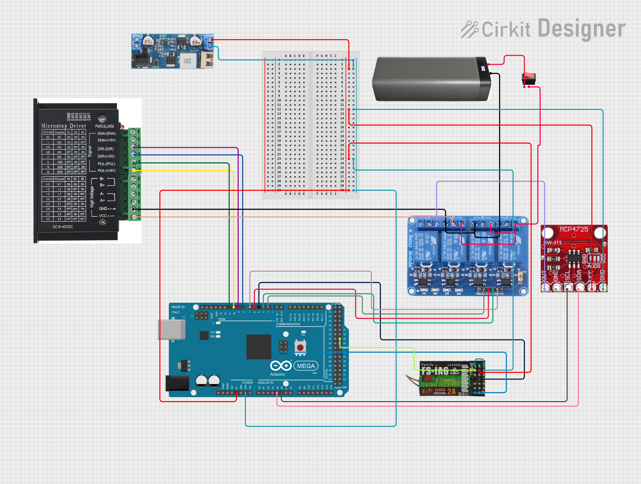

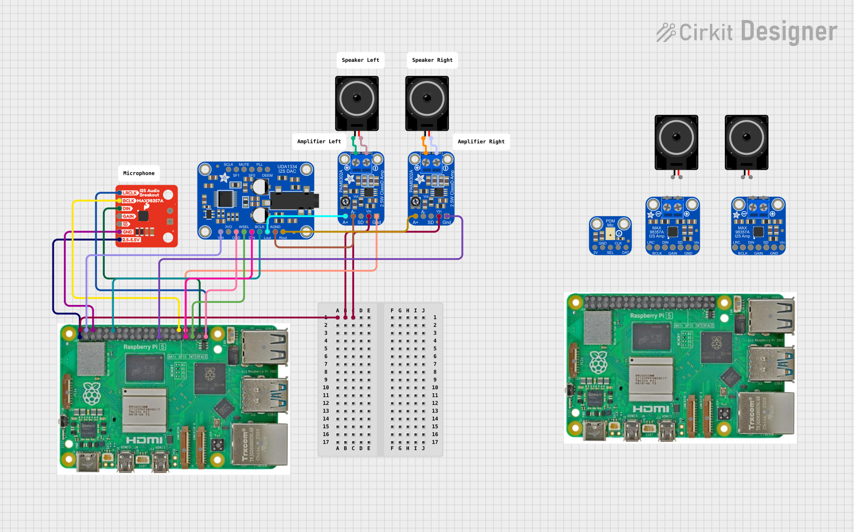
Explore Projects Built with Analog to Digital Converter (DAC)
Common Applications and Use Cases
- Sensor Data Acquisition: Reading analog signals from sensors like temperature, pressure, or light sensors.
- Audio Processing: Converting analog audio signals into digital data for processing or storage.
- Signal Monitoring: Used in oscilloscopes and data loggers to digitize analog waveforms.
- Embedded Systems: Interfacing with microcontrollers for real-time data processing.
Technical Specifications
Below are the general technical specifications for a typical ADC. Note that specific ADC models may vary in their parameters.
Key Technical Details
- Resolution: 8-bit, 10-bit, 12-bit, 16-bit, or higher (determines the precision of conversion).
- Input Voltage Range: Typically 0V to 5V or 0V to 3.3V (depending on the ADC and system voltage).
- Sampling Rate: Ranges from a few kSPS (kilo-samples per second) to several MSPS (mega-samples per second).
- Interface: Parallel, SPI, I2C, or UART communication protocols.
- Power Supply Voltage: Commonly 3.3V or 5V.
- Input Impedance: High impedance to minimize signal loading.
- Accuracy: Depends on resolution and noise levels, typically ±1 LSB (Least Significant Bit).
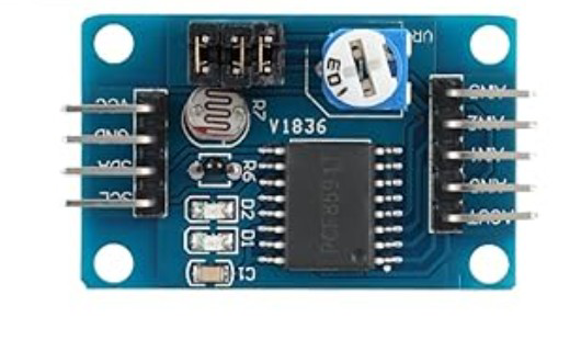
Pin Configuration and Descriptions
Below is a typical pinout for an ADC IC (e.g., MCP3008, a popular 10-bit ADC):
| Pin Name | Description |
|---|---|
| VDD | Positive power supply (e.g., 3.3V or 5V). |
| VSS | Ground connection. |
| CH0-CH7 | Analog input channels (e.g., CH0 for single-ended input or CH0-CH1 for differential). |
| CS/SHDN | Chip Select or Shutdown pin (used to enable/disable the ADC). |
| DIN | Data input pin for SPI communication. |
| DOUT | Data output pin for SPI communication. |
| CLK | Clock input for SPI communication. |
| VREF | Reference voltage input (sets the maximum input voltage for the ADC). |
Usage Instructions
How to Use the ADC in a Circuit
- Power the ADC: Connect the VDD pin to the appropriate power supply (e.g., 3.3V or 5V) and the VSS pin to ground.
- Connect the Analog Signal: Attach the analog signal source (e.g., a sensor) to one of the analog input pins (e.g., CH0).
- Set the Reference Voltage: Connect a stable reference voltage to the VREF pin. This voltage determines the maximum input range for the ADC.
- Interface with a Microcontroller: Use the appropriate communication protocol (e.g., SPI) to connect the ADC to a microcontroller or processor.
- Read Digital Data: Send commands to the ADC to initiate a conversion and read the resulting digital data.
Important Considerations and Best Practices
- Input Signal Conditioning: Use filters or amplifiers to ensure the input signal is within the ADC's voltage range and free of noise.
- Reference Voltage Stability: Use a precise and stable reference voltage to improve conversion accuracy.
- Sampling Rate: Choose a sampling rate that is appropriate for the signal frequency to avoid aliasing (Nyquist theorem).
- Bypass Capacitors: Place decoupling capacitors near the power supply pins to reduce noise.
Example: Using MCP3008 ADC with Arduino UNO
Below is an example of interfacing the MCP3008 ADC with an Arduino UNO to read an analog signal:
#include <SPI.h>

// Define MCP3008 pins
const int CS_PIN = 10; // Chip Select pin connected to Arduino pin 10

void setup() {
  Serial.begin(9600); // Initialize serial communication
  SPI.begin();        // Initialize SPI communication
  pinMode(CS_PIN, OUTPUT); // Set CS pin as output
  digitalWrite(CS_PIN, HIGH); // Set CS pin to HIGH (inactive)
}

int readADC(int channel) {
  // Ensure the channel is within valid range (0-7)
  if (channel < 0 || channel > 7) return -1;

  digitalWrite(CS_PIN, LOW); // Activate the ADC by setting CS LOW

  // Send start bit, single-ended mode, and channel selection
  byte command = 0b00000001; // Start bit
  byte config = (channel << 4) | 0b10000000; // Channel and mode
  SPI.transfer(command); // Send start bit
  byte highByte = SPI.transfer(config); // Send config and receive high byte
  byte lowByte = SPI.transfer(0x00); // Receive low byte

  digitalWrite(CS_PIN, HIGH); // Deactivate the ADC by setting CS HIGH

  // Combine high and low bytes into a 10-bit result
  int result = ((highByte & 0x03) << 8) | lowByte;
  return result;
}

void loop() {
  int adcValue = readADC(0); // Read from channel 0
  Serial.print("ADC Value: ");
  Serial.println(adcValue); // Print the ADC value
  delay(500); // Wait for 500ms
}
Troubleshooting and FAQs
Common Issues and Solutions
No Output or Incorrect Readings:
- Cause: Incorrect wiring or loose connections.
- Solution: Double-check all connections, especially power, ground, and communication lines.
Noisy or Fluctuating Readings:
- Cause: Input signal noise or unstable reference voltage.
- Solution: Use proper filtering (e.g., low-pass filter) and a stable reference voltage source.
ADC Not Responding:
- Cause: Incorrect SPI configuration or chip select handling.
- Solution: Verify SPI settings (clock polarity, phase, and speed) and ensure the CS pin is toggled correctly.
Out-of-Range Values:
- Cause: Input signal exceeds the ADC's voltage range.
- Solution: Ensure the input signal is within the ADC's specified range (e.g., 0V to VREF).
FAQs
Q: Can I use an ADC with a 3.3V system on a 5V microcontroller?
- A: Yes, but ensure proper level shifting for communication lines and verify that the ADC's input voltage range matches the system.
Q: How do I improve ADC accuracy?
- A: Use a high-resolution ADC, a stable reference voltage, and proper signal conditioning.
Q: What is the difference between single-ended and differential inputs?
- A: Single-ended inputs measure the voltage relative to ground, while differential inputs measure the voltage difference between two input pins.
This concludes the documentation for the Analog to Digital Converter (ADC).