Cirkit Designer Logo
Cirkit Designer
Your all-in-one circuit design IDE
Home / 
Component Documentation

How to Use Diode: Examples, Pinouts, and Specs

Image of Diode
Cirkit Designer LogoDesign with Diode in Cirkit Designer

Introduction

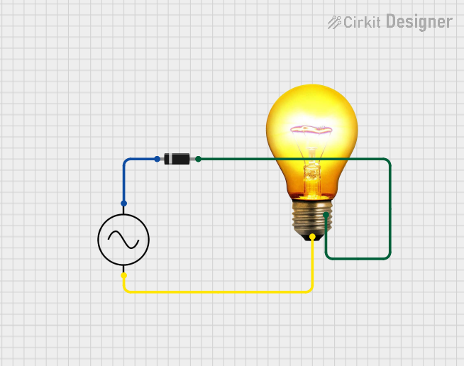
A diode is a semiconductor device that allows current to flow in one direction only, acting as a one-way valve for electric current. Diodes are commonly used in various applications such as rectifying alternating current (AC) to direct current (DC), overvoltage protection, voltage regulation, signal demodulation, and more.

Explore Projects Built with Diode

Use Cirkit Designer to design, explore, and prototype these projects online. Some projects support real-time simulation. Click "Open Project" to start designing instantly!
Resistor-Diode Circuit with Multimeter Current Measurement
Image of diode: A project utilizing Diode in a practical application
This circuit consists of a power supply connected in series with a resistor and a diode. A multimeter is connected across the resistor to measure the current flowing through the resistor. The diode ensures current flows in one direction, protecting the circuit from potential reverse current damage.
Cirkit Designer LogoOpen Project in Cirkit Designer
Diode-Resistor Network for Voltage Regulation
Image of Feed bot cirkit: A project utilizing Diode in a practical application
This circuit consists of two parallel branches, each containing an 820 Ohm resistor in series with a diode. The anodes of both diodes are connected together, forming a common node.
Cirkit Designer LogoOpen Project in Cirkit Designer
Diode and Capacitor-Based Voltage Regulation Circuit
Image of Pavetra#2: A project utilizing Diode in a practical application
This circuit is a complex network of diodes and electrolytic capacitors connected to two terminal PCB 2-pin connectors. The diodes are arranged in a series-parallel configuration, while the capacitors are connected in a manner that suggests filtering or energy storage purposes. The overall design appears to be aimed at rectification and smoothing of an input signal.
Cirkit Designer LogoOpen Project in Cirkit Designer
AC Power Supply with Diode Rectification and Bulb Indicator
Image of susa: A project utilizing Diode in a practical application
This circuit is a simple AC-powered light with a diode in series. The diode is connected in series with the AC supply's positive terminal and the AC bulb's neutral terminal, while the bulb's positive terminal is connected to the AC supply's negative terminal. The diode will rectify the AC current, allowing only one half of the AC waveform to pass through to the bulb, causing it to flicker at a rate of half the AC frequency.
Cirkit Designer LogoOpen Project in Cirkit Designer

Explore Projects Built with Diode

Use Cirkit Designer to design, explore, and prototype these projects online. Some projects support real-time simulation. Click "Open Project" to start designing instantly!
Image of diode: A project utilizing Diode in a practical application
Resistor-Diode Circuit with Multimeter Current Measurement
This circuit consists of a power supply connected in series with a resistor and a diode. A multimeter is connected across the resistor to measure the current flowing through the resistor. The diode ensures current flows in one direction, protecting the circuit from potential reverse current damage.
Cirkit Designer LogoOpen Project in Cirkit Designer
Image of Feed bot cirkit: A project utilizing Diode in a practical application
Diode-Resistor Network for Voltage Regulation
This circuit consists of two parallel branches, each containing an 820 Ohm resistor in series with a diode. The anodes of both diodes are connected together, forming a common node.
Cirkit Designer LogoOpen Project in Cirkit Designer
Image of Pavetra#2: A project utilizing Diode in a practical application
Diode and Capacitor-Based Voltage Regulation Circuit
This circuit is a complex network of diodes and electrolytic capacitors connected to two terminal PCB 2-pin connectors. The diodes are arranged in a series-parallel configuration, while the capacitors are connected in a manner that suggests filtering or energy storage purposes. The overall design appears to be aimed at rectification and smoothing of an input signal.
Cirkit Designer LogoOpen Project in Cirkit Designer
Image of susa: A project utilizing Diode in a practical application
AC Power Supply with Diode Rectification and Bulb Indicator
This circuit is a simple AC-powered light with a diode in series. The diode is connected in series with the AC supply's positive terminal and the AC bulb's neutral terminal, while the bulb's positive terminal is connected to the AC supply's negative terminal. The diode will rectify the AC current, allowing only one half of the AC waveform to pass through to the bulb, causing it to flicker at a rate of half the AC frequency.
Cirkit Designer LogoOpen Project in Cirkit Designer

Technical Specifications

Key Technical Details

  • Forward Voltage (Vf): The voltage drop across the diode when it is conducting current.
  • Reverse Breakdown Voltage (Vr): The maximum reverse voltage the diode can withstand without breaking down.
  • Maximum Forward Current (If): The maximum current the diode can conduct without damage.
  • Reverse Leakage Current (Ir): The small current that flows through the diode when reverse-biased.
  • Power Dissipation (Pd): The maximum power the diode can dissipate without damage.

Pin Configuration and Descriptions

Pin Number Name Description
1 Anode The terminal where current enters the diode.
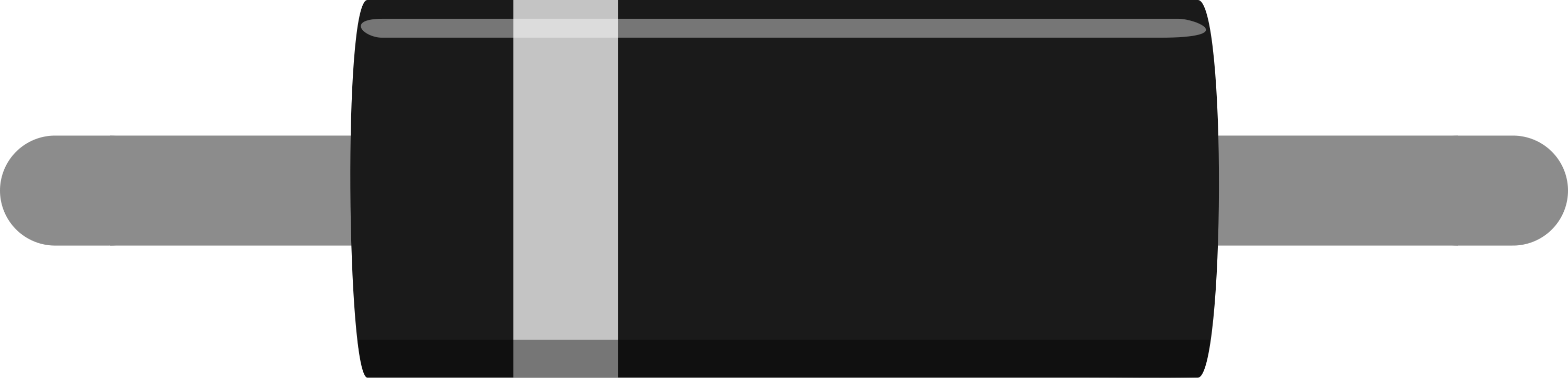
2 Cathode The terminal where current exits the diode, marked with a stripe.

Usage Instructions

How to Use the Diode in a Circuit

  1. Identify the Anode and Cathode: The anode is the positive side, and the cathode is usually marked with a stripe.
  2. Forward Bias Connection: Connect the anode to the positive voltage and the cathode to the negative side of the circuit to allow current flow.
  3. Reverse Bias Connection: Reverse the connections to block current flow, useful for protection against reverse polarity.

Important Considerations and Best Practices

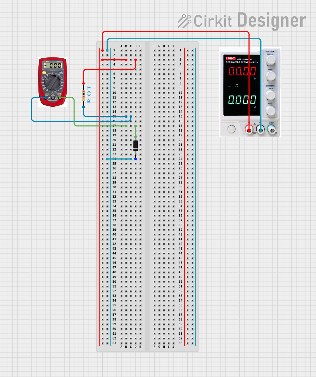
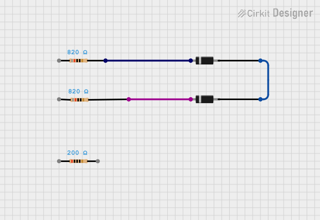
  • Current Limiting: Always use a current-limiting resistor to prevent excessive current through the diode.
  • Heat Management: Ensure proper heat sinking if the diode is expected to dissipate significant power.
  • Reverse Voltage Protection: Use a diode in reverse bias across power inputs to protect against reverse voltage damage.

Troubleshooting and FAQs

Common Issues

  • Diode Not Conducting: Ensure the diode is forward-biased and that the forward voltage is sufficient.
  • Excessive Heat: Check if the current exceeds the maximum rating or if proper heat sinking is in place.
  • Unexpected Voltage Drops: Verify that the forward voltage drop is within the expected range for the diode type.

Solutions and Tips

  • Use a Multimeter: To check if a diode is functioning, use a multimeter in diode mode to measure the forward and reverse bias voltages.
  • Replace if Faulty: If the diode shows an open circuit in both directions or a short circuit, replace it.

FAQs

Q: Can I use any diode for reverse voltage protection? A: No, you must use a diode that can handle the maximum reverse voltage and current of your circuit.

Q: What happens if I exceed the maximum forward current of a diode? A: The diode may overheat and fail, potentially damaging the circuit.

Q: How do I choose the right diode for my application? A: Consider the maximum forward current, the reverse breakdown voltage, and the power dissipation based on your circuit's requirements.

Example Code for Arduino UNO

If you're using a diode with an Arduino UNO to protect against reverse voltage, no code is needed. However, if you're using a diode to control the flow of current to an LED, here's a simple example:

// Define the LED pin
const int ledPin = 13;

void setup() {
  // Set the LED pin as an output
  pinMode(ledPin, OUTPUT);
}

void loop() {
  // Turn on the LED
  digitalWrite(ledPin, HIGH);
  delay(1000); // Wait for 1 second
  // Turn off the LED
  digitalWrite(ledPin, LOW);
  delay(1000); // Wait for 1 second
}

In this example, a diode would be placed in series with the LED to ensure current only flows in the correct direction, protecting the LED from reverse current. Remember to consider the forward voltage drop of the diode when calculating the current-limiting resistor for the LED.