How to Use Socket PTF08A: Examples, Pinouts, and Specs
Introduction
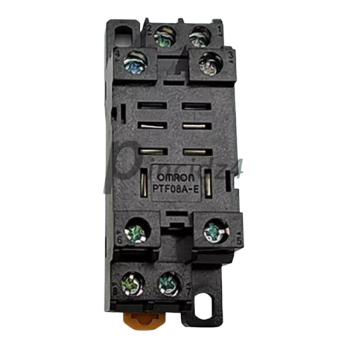
The Socket PTF08A is a versatile and reliable 8-pin socket designed for connecting integrated circuits (ICs) to printed circuit boards (PCBs). It features a pin grid array that ensures secure and stable connections, making it an essential component for prototyping, testing, and permanent circuit installations. The socket allows for easy insertion and removal of ICs without the risk of damaging the IC pins or the PCB.
Explore Projects Built with Socket PTF08A


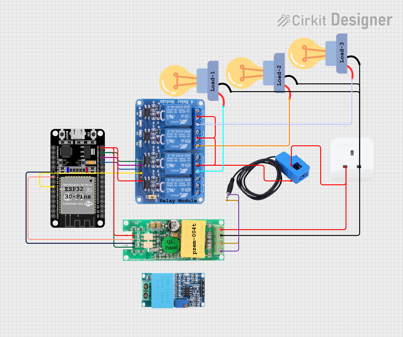
Explore Projects Built with Socket PTF08A
Common Applications and Use Cases
- Prototyping and testing circuits with 8-pin ICs
- Protecting ICs from soldering heat during PCB assembly
- Facilitating IC replacement in repairable designs
- Used in applications such as timers (e.g., NE555), operational amplifiers, and small-scale logic circuits
Technical Specifications
The Socket PTF08A is designed to accommodate 8-pin dual in-line package (DIP) ICs. Below are its key technical details:
Key Specifications
- Number of Pins: 8
- Pin Pitch: 2.54 mm (standard DIP spacing)
- Material: High-quality thermoplastic body with phosphor bronze contacts
- Contact Plating: Tin or gold (varies by manufacturer)
- Operating Temperature: -40°C to +105°C
- Insertion Force: Low, for easy IC insertion
- Retention Force: High, for secure IC placement
- Mounting Type: Through-hole
Pin Configuration and Descriptions
The Socket PTF08A does not have specific pin functionality, as it is a passive component designed to hold ICs. However, the pin layout corresponds directly to the IC it houses. Below is a general representation of the pin configuration:
| Pin Number | Description |
|---|---|
| 1 | IC Pin 1 Connection |
| 2 | IC Pin 2 Connection |
| 3 | IC Pin 3 Connection |
| 4 | IC Pin 4 Connection |
| 5 | IC Pin 5 Connection |
| 6 | IC Pin 6 Connection |
| 7 | IC Pin 7 Connection |
| 8 | IC Pin 8 Connection |
Usage Instructions
How to Use the Socket PTF08A in a Circuit
- Prepare the PCB: Ensure the PCB has an 8-pin DIP footprint with through-hole pads matching the socket's pin layout.
- Insert the Socket: Place the socket into the PCB, aligning its pins with the corresponding holes.
- Solder the Pins: Solder each pin to the PCB, ensuring clean and secure connections. Avoid excessive solder that could cause shorts.
- Insert the IC: Carefully align the IC pins with the socket and press it gently into place. Ensure proper orientation by matching the IC's notch or dot with the socket's marking.
- Test the Circuit: Power on the circuit and verify the IC's functionality.
Important Considerations and Best Practices
- Orientation: Always check the orientation of the IC before insertion to avoid damage.
- Soldering: Use a temperature-controlled soldering iron to prevent overheating the socket or PCB.
- IC Removal: Use an IC extractor tool to safely remove the IC without bending or damaging its pins.
- Compatibility: Ensure the socket is compatible with the IC's pin count and pitch.
Example: Using the Socket PTF08A with an Arduino UNO
The Socket PTF08A can be used to house an 8-pin IC, such as the NE555 timer, in a circuit connected to an Arduino UNO. Below is an example of using the NE555 timer to generate a square wave signal:
/* Example: Using NE555 Timer with Arduino UNO
   This code demonstrates how to read a square wave signal generated by
   an NE555 timer housed in a PTF08A socket. The signal is read on pin 2.
*/

const int signalPin = 2; // Pin connected to the NE555 output
int signalState = 0;     // Variable to store the signal state

void setup() {
  pinMode(signalPin, INPUT); // Set signal pin as input
  Serial.begin(9600);       // Initialize serial communication
}

void loop() {
  signalState = digitalRead(signalPin); // Read the signal state
  Serial.println(signalState);         // Print the signal state to the Serial Monitor
  delay(100);                          // Delay for readability
}
Troubleshooting and FAQs
Common Issues and Solutions
Loose IC Connection
- Issue: The IC feels loose or does not make proper contact.
- Solution: Ensure the IC pins are straight and properly aligned with the socket. Check for debris or damage in the socket.
Soldering Problems
- Issue: Poor solder joints or solder bridges between pins.
- Solution: Re-solder the pins using a clean soldering tip and appropriate soldering technique.
IC Orientation
- Issue: The IC does not function as expected.
- Solution: Verify the IC is inserted in the correct orientation by matching the notch or dot on the IC with the socket marking.
Damaged Socket Pins
- Issue: One or more socket pins are bent or broken.
- Solution: Replace the socket with a new one to ensure reliable connections.
FAQs
Q: Can the Socket PTF08A be reused?
- A: Yes, the socket is designed for multiple insertions and removals of ICs, making it reusable.
Q: Is the Socket PTF08A compatible with surface-mount ICs?
- A: No, the socket is designed for through-hole DIP ICs only.
Q: How do I clean the socket if it gets dirty?
- A: Use compressed air or a soft brush to remove debris. Avoid using liquids that could damage the contacts.
Q: Can I use the socket for ICs with fewer than 8 pins?
- A: Yes, but ensure the IC pins align with the correct socket pins for proper functionality.
This concludes the documentation for the Socket PTF08A.