How to Use Relay PYF-8: Examples, Pinouts, and Specs
Introduction
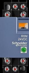
The Relay PYF-8 is a socket relay designed for switching applications. It allows for the control of high voltage and current loads using a low voltage signal, providing isolation and protection for sensitive components in a circuit. Manufactured for 230V applications, this relay is widely used in industrial automation, home appliances, and control systems. Its robust design ensures reliable operation in demanding environments.
Explore Projects Built with Relay PYF-8
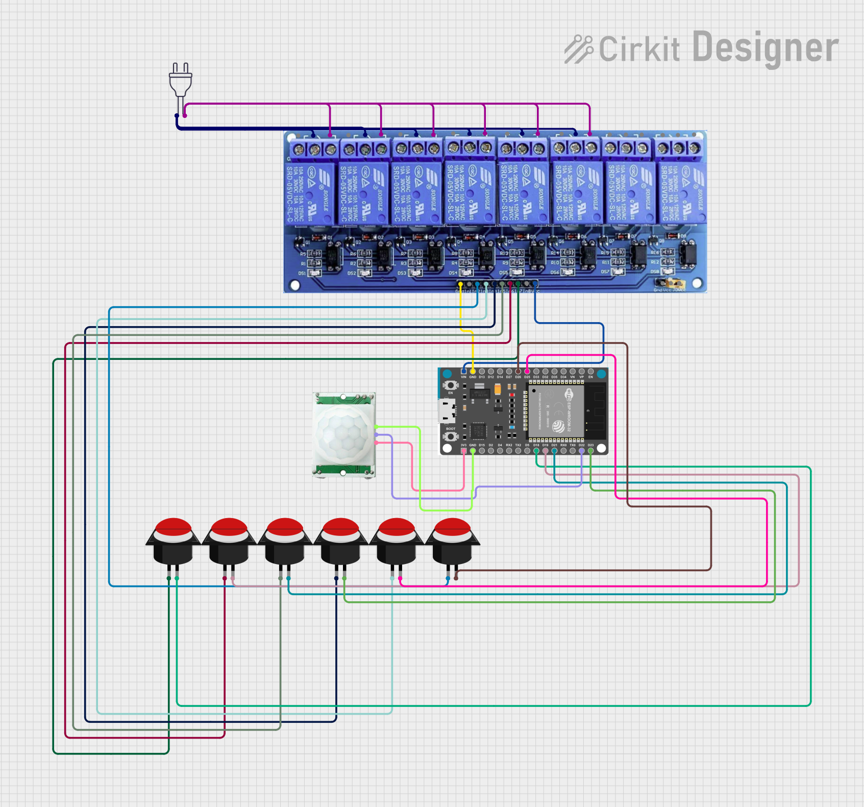


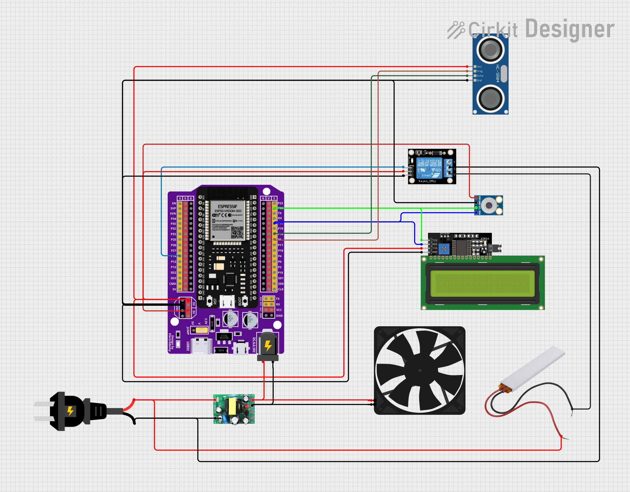
Explore Projects Built with Relay PYF-8
Common Applications
- Industrial automation systems
- Home appliance control (e.g., HVAC systems)
- Motor control circuits
- Lighting systems
- Safety and protection circuits
Technical Specifications
Key Technical Details
| Parameter | Value |
|---|---|
| Operating Voltage | 230V AC |
| Coil Voltage | 12V DC |
| Contact Configuration | SPDT (Single Pole Double Throw) |
| Contact Rating | 10A at 250V AC / 10A at 30V DC |
| Insulation Resistance | ≥ 100 MΩ at 500V DC |
| Dielectric Strength | 2000V AC for 1 minute |
| Operating Temperature | -40°C to +70°C |
| Mounting Type | Socket mount |
| Dimensions | 34mm x 28mm x 25mm |
Pin Configuration and Descriptions
The Relay PYF-8 has 8 pins, which are configured as follows:
| Pin Number | Description |
|---|---|
| 1 | Coil Terminal 1 (Positive) |
| 2 | Coil Terminal 2 (Negative) |
| 3 | Common Contact (COM) |
| 4 | Normally Open Contact (NO) |
| 5 | Normally Closed Contact (NC) |
| 6, 7, 8 | Additional socket connections for stability |
Usage Instructions
How to Use the Relay PYF-8 in a Circuit
- Power the Coil: Connect the coil terminals (Pin 1 and Pin 2) to a 12V DC power source. Ensure the polarity is correct.
- Connect the Load:
- Connect the load to the Common (COM) terminal (Pin 3).
- Use the Normally Open (NO) terminal (Pin 4) if you want the load to be powered only when the relay is activated.
- Use the Normally Closed (NC) terminal (Pin 5) if you want the load to be powered when the relay is not activated.
- Control the Relay: Use a low voltage control signal (e.g., from a microcontroller or switch) to activate the relay coil.
Important Considerations
- Isolation: Ensure proper isolation between the high voltage and low voltage sides of the circuit.
- Flyback Diode: When using the relay with a microcontroller, connect a flyback diode across the coil terminals to protect the control circuit from voltage spikes.
- Current Rating: Do not exceed the relay's contact rating (10A at 250V AC or 10A at 30V DC).
- Mounting: Securely mount the relay in its socket to ensure stable operation.
Example: Connecting the Relay PYF-8 to an Arduino UNO
Below is an example of how to control the Relay PYF-8 using an Arduino UNO:
// Define the pin connected to the relay's coil
const int relayPin = 7;

void setup() {
  pinMode(relayPin, OUTPUT); // Set the relay pin as an output
  digitalWrite(relayPin, LOW); // Ensure the relay is off initially
}

void loop() {
  digitalWrite(relayPin, HIGH); // Activate the relay
  delay(1000); // Keep the relay on for 1 second
  digitalWrite(relayPin, LOW); // Deactivate the relay
  delay(1000); // Keep the relay off for 1 second
}
Note: Use a transistor or relay driver circuit to interface the Arduino with the relay, as the Arduino's GPIO pins cannot directly supply enough current to drive the relay coil.
Troubleshooting and FAQs
Common Issues and Solutions
Relay Not Activating:
- Cause: Insufficient voltage or current to the coil.
- Solution: Verify the coil voltage is 12V DC and the power supply can provide sufficient current.
Load Not Switching:
- Cause: Incorrect wiring of the load to the relay terminals.
- Solution: Double-check the connections to the COM, NO, and NC terminals.
Voltage Spikes Damaging the Circuit:
- Cause: Lack of a flyback diode across the coil terminals.
- Solution: Install a flyback diode (e.g., 1N4007) across the coil terminals with the cathode connected to the positive terminal.
Relay Overheating:
- Cause: Exceeding the contact current rating.
- Solution: Ensure the load current does not exceed 10A.
FAQs
Q1: Can the Relay PYF-8 be used with a 5V control signal?
A1: No, the relay coil requires a 12V DC signal. Use a transistor or relay driver circuit to step up the control signal.
Q2: Is the Relay PYF-8 suitable for DC loads?
A2: Yes, it can handle DC loads up to 10A at 30V DC.
Q3: Can I use the relay without a socket?
A3: While possible, it is recommended to use the relay with its designated socket for secure mounting and reliable connections.
Q4: What is the purpose of the NC terminal?
A4: The NC terminal allows the load to remain powered when the relay is not activated, providing a default "on" state.