How to Use Graphic LCD Display (GLCD 128x64): Examples, Pinouts, and Specs
Introduction
The Graphic LCD Display (GLCD 128x64) is a versatile graphical liquid crystal display with a resolution of 128x64 pixels. It is widely used in embedded systems and applications to display images, graphics, and text. Unlike character LCDs, the GLCD allows for more complex visual outputs, making it ideal for projects requiring detailed graphical interfaces.
Explore Projects Built with Graphic LCD Display (GLCD 128x64)


Explore Projects Built with Graphic LCD Display (GLCD 128x64)
Common Applications and Use Cases
- Embedded systems with graphical user interfaces (GUIs)
- Industrial control panels
- Medical devices
- DIY electronics projects
- Robotics and automation systems
- Educational tools for learning about graphical displays
Technical Specifications
Below are the key technical details and pin configuration for the GLCD 128x64:
Key Technical Details
| Parameter | Value |
|---|---|
| Display Type | Graphical LCD |
| Resolution | 128x64 pixels |
| Operating Voltage | 4.5V to 5.5V |
| Backlight Voltage | 4.2V to 4.5V |
| Current Consumption | ~20mA (without backlight) |
| Interface Type | Parallel (8-bit or 4-bit mode) |
| Controller IC | KS0108 or equivalent |
| Operating Temperature | -20°C to +70°C |
| Dimensions | ~93mm x 70mm x 12mm |
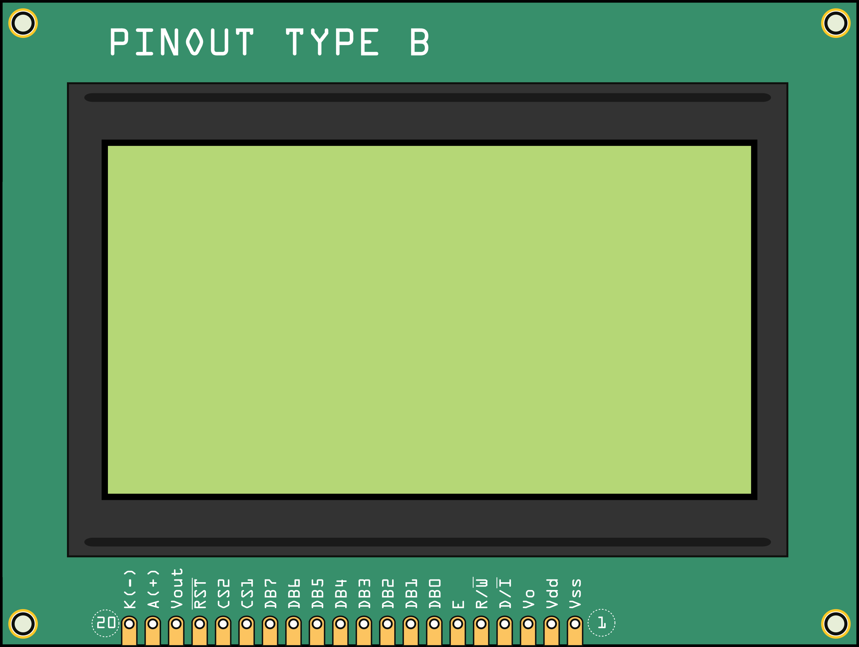
Pin Configuration and Descriptions
The GLCD 128x64 typically has a 20-pin interface. Below is the pinout and description:
| Pin No. | Name | Description |
|---|---|---|
| 1 | VSS | Ground (0V) |
| 2 | VDD | Power supply (+5V) |
| 3 | VO | Contrast adjustment (connect to a potentiometer) |
| 4 | RS | Register Select (0: Command, 1: Data) |
| 5 | R/W | Read/Write control (0: Write, 1: Read) |
| 6 | E | Enable signal (triggers data read/write) |
| 7-14 | DB0-DB7 | Data bus lines (DB0: LSB, DB7: MSB) |
| 15 | CS1 | Chip Select 1 (activates left half of the display) |
| 16 | CS2 | Chip Select 2 (activates right half of the display) |
| 17 | RST | Reset signal (active low) |
| 18 | VEE | Negative voltage output for contrast control |
| 19 | A | Backlight anode (+) |
| 20 | K | Backlight cathode (-) |
Usage Instructions
How to Use the Component in a Circuit
- Power Supply: Connect the
VSSpin to ground and theVDDpin to a 5V power source. - Contrast Adjustment: Use a 10kΩ potentiometer connected to the
VOpin to adjust the display contrast. - Data and Control Lines: Connect the
RS,R/W, andEpins to the microcontroller for control signals. Use theDB0-DB7pins for data transfer. - Chip Select: Use the
CS1andCS2pins to activate the left and right halves of the display, respectively. - Backlight: Connect the
AandKpins to power the backlight. Use a current-limiting resistor if necessary.
Important Considerations and Best Practices
- Ensure the power supply voltage is stable and within the specified range to avoid damage.
- Use decoupling capacitors (e.g., 0.1µF) near the power pins to reduce noise.
- Avoid leaving unused data pins floating; connect them to ground if not in use.
- For optimal contrast, adjust the potentiometer connected to the
VOpin carefully. - Use a compatible library (e.g.,
U8gliborGLCD) for easier interfacing with microcontrollers.
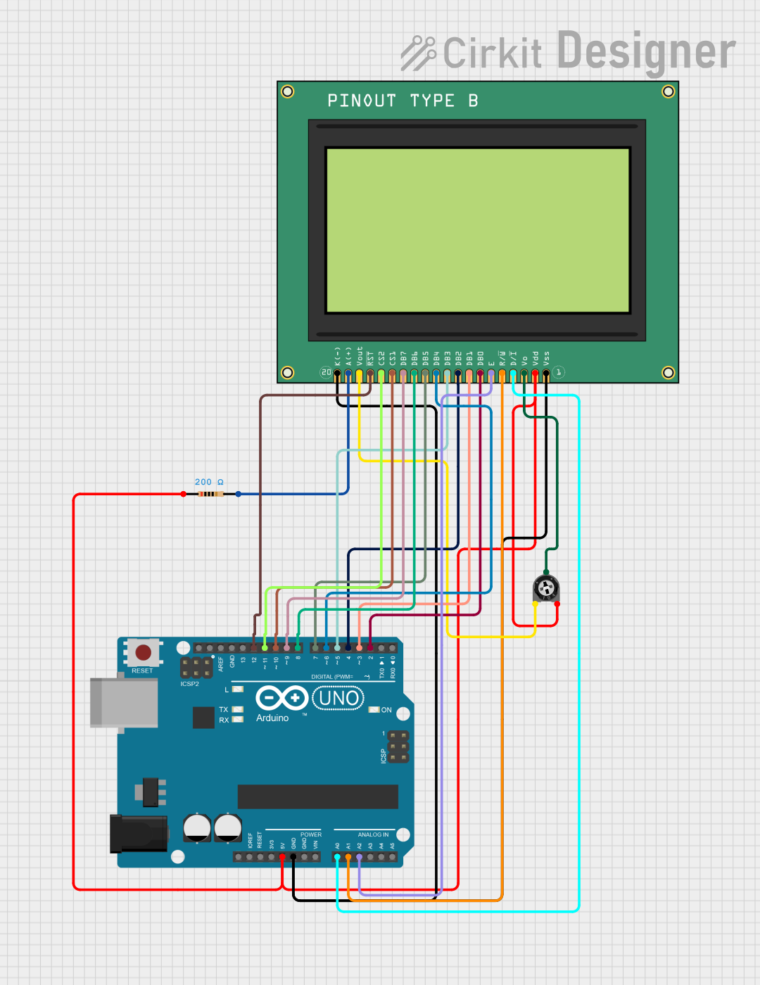
Example: Connecting to an Arduino UNO
Below is an example of how to connect and program the GLCD 128x64 with an Arduino UNO using the U8glib library:
Wiring Diagram
| GLCD Pin | Arduino Pin |
|---|---|
| VSS | GND |
| VDD | 5V |
| VO | Potentiometer (middle pin) |
| RS | Pin 9 |
| R/W | GND |
| E | Pin 8 |
| DB0-DB7 | Pins 2-7 |
| CS1 | Pin 10 |
| CS2 | Pin 11 |
| RST | Pin 12 |
| A | 5V (via resistor) |
| K | GND |
Arduino Code Example
#include <U8glib.h>

// Initialize the GLCD with the KS0108 controller
U8GLIB_KS0108 glcd(U8G_PIN_NONE, 10, 11, 12, 9, 8, 7, 6, 5, 4, 3, 2);

void setup() {
  // Begin communication with the GLCD
  glcd.begin();
}

void loop() {
  // Clear the display
  glcd.firstPage();
  do {
    // Draw a simple message
    glcd.setFont(u8g_font_6x10); // Set font size
    glcd.drawStr(10, 20, "Hello, GLCD!"); // Display text
  } while (glcd.nextPage());

  delay(1000); // Wait for 1 second
}
Notes:
- Install the
U8gliblibrary in the Arduino IDE before uploading the code. - Adjust the pin numbers in the code to match your wiring if necessary.
Troubleshooting and FAQs
Common Issues and Solutions
No Display Output:
- Check the power connections (
VSSandVDD). - Ensure the contrast is properly adjusted using the potentiometer.
- Verify the
CS1andCS2pins are correctly configured.
- Check the power connections (
Flickering or Unstable Display:
- Add decoupling capacitors near the power pins.
- Ensure the backlight current is within the recommended range.
Incorrect or Garbled Graphics:
- Verify the data and control pin connections.
- Ensure the correct library and controller type (e.g., KS0108) are used in the code.
Backlight Not Working:
- Check the
AandKpin connections. - Use a suitable resistor to limit the current to the backlight.
- Check the
FAQs
Q: Can I use the GLCD 128x64 with a 3.3V microcontroller?
A: Yes, but you will need a level shifter to convert the 3.3V logic to 5V for proper operation.
Q: What is the maximum cable length for connecting the GLCD?
A: Keep the cable length as short as possible (preferably under 30cm) to avoid signal degradation.
Q: Can I display images on the GLCD?
A: Yes, you can display bitmap images by converting them into a compatible format using tools like LCD Assistant.
Q: Is the GLCD compatible with SPI or I2C?
A: No, the GLCD 128x64 uses a parallel interface. However, you can use an external adapter to convert it to SPI or I2C.