How to Use esp12e motor shield: Examples, Pinouts, and Specs
Introduction
The ESP12E Motor Shield is a versatile add-on board designed specifically for the ESP12E Wi-Fi module. It simplifies the process of controlling DC motors and stepper motors, making it an excellent choice for robotics, automation, and IoT projects. The shield provides dedicated motor driver circuitry, power supply interfaces, and additional sensor connections, enabling seamless integration into motorized systems.
Explore Projects Built with esp12e motor shield


Explore Projects Built with esp12e motor shield
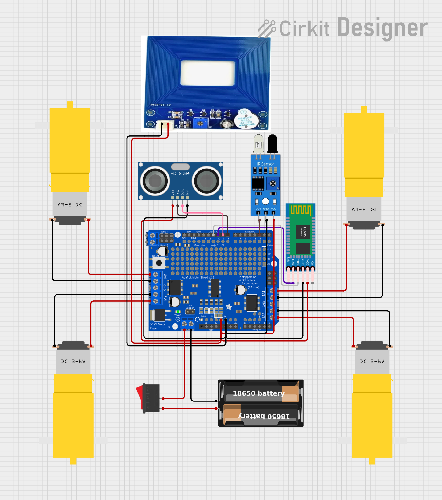
Common Applications and Use Cases
- Robotics projects requiring motor control
- Home automation systems with motorized components
- IoT devices with moving parts
- Prototyping motorized mechanisms
- Educational projects for learning motor control and IoT integration
Technical Specifications
Key Technical Details
- Input Voltage (Logic): 3.3V (compatible with ESP12E logic levels)
- Motor Voltage Range: 6V to 12V (external power supply required)
- Motor Driver IC: L298N dual H-bridge driver
- Maximum Motor Current: 2A per channel
- Supported Motors: DC motors and stepper motors
- Communication Interface: GPIO pins of the ESP12E module
- Additional Features:
- Screw terminals for motor connections
- External power input with reverse polarity protection
- Breakout pins for sensors and peripherals
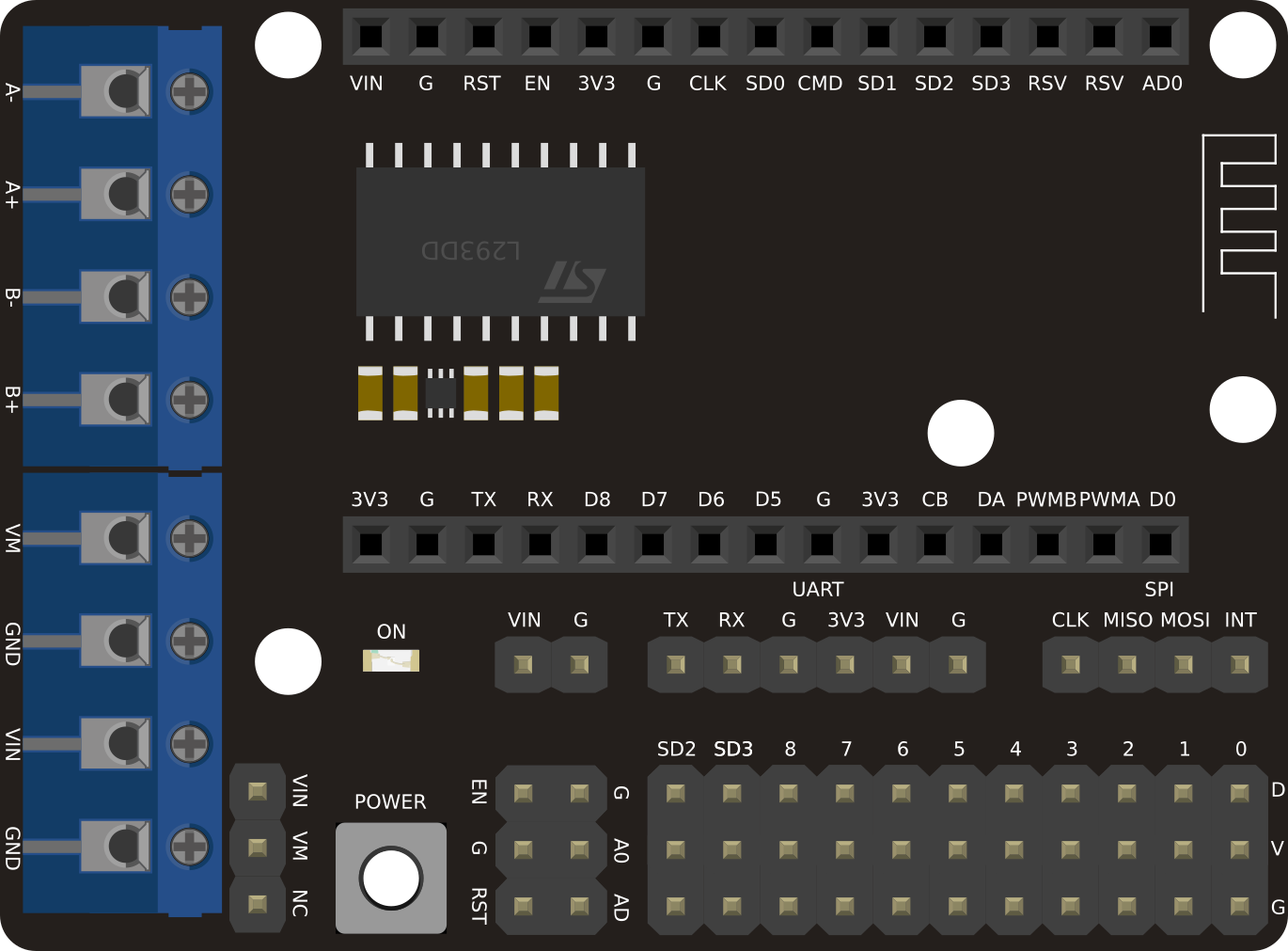
Pin Configuration and Descriptions
The ESP12E Motor Shield has several key pin interfaces for motor control and additional functionality. Below is a detailed description of the pin configuration:
Motor Control Pins
| Pin Name | Description |
|---|---|
| IN1 | Control signal for Motor A (forward) |
| IN2 | Control signal for Motor A (reverse) |
| IN3 | Control signal for Motor B (forward) |
| IN4 | Control signal for Motor B (reverse) |
| ENA | Enable pin for Motor A (PWM control) |
| ENB | Enable pin for Motor B (PWM control) |
Power and Sensor Pins
| Pin Name | Description |
|---|---|
| VIN | External motor power supply (6-12V) |
| GND | Ground connection |
| 3.3V | Logic power supply for ESP12E |
| Sensor Pins | Breakout pins for connecting sensors |
Usage Instructions
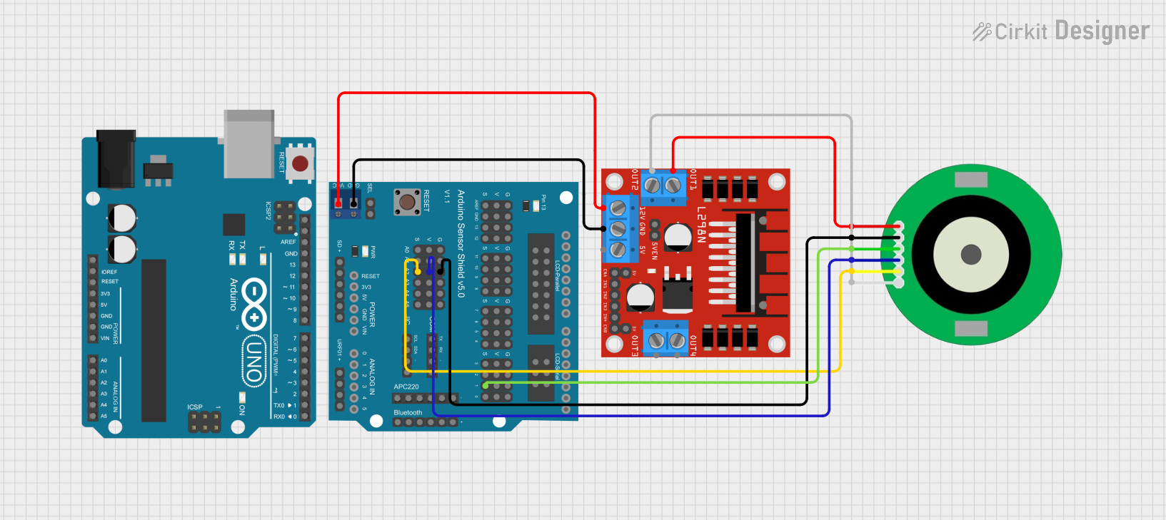
How to Use the ESP12E Motor Shield in a Circuit
Connect the ESP12E Module:
- Mount the ESP12E module onto the motor shield, ensuring proper alignment with the pin headers.
Connect Motors:
- Use the screw terminals to connect DC motors or stepper motors to the shield.
- For DC motors, connect one motor to the Motor A terminals and another to the Motor B terminals.
Power the Shield:
- Provide an external power supply (6-12V) to the VIN and GND terminals for motor operation.
- Ensure the power supply can handle the current requirements of the motors.
Control the Motors:
- Use the ESP12E GPIO pins to send control signals (HIGH/LOW) to the IN1, IN2, IN3, and IN4 pins.
- Use PWM signals on the ENA and ENB pins to control motor speed.
Important Considerations and Best Practices
- Power Supply: Always use a power supply that matches the voltage and current requirements of your motors.
- Heat Dissipation: The L298N driver IC may heat up during operation. Consider adding a heat sink or fan for prolonged use.
- Reverse Polarity Protection: Ensure correct polarity when connecting the external power supply to avoid damage.
- Sensor Integration: Use the breakout pins to connect additional sensors for advanced functionality, such as obstacle detection or position tracking.
Example Code for Arduino UNO
If you are using the ESP12E Motor Shield with an Arduino UNO for prototyping, here is an example code snippet to control two DC motors:
// Define motor control pins
#define IN1 5  // Motor A forward
#define IN2 4  // Motor A reverse
#define ENA 6  // Motor A speed (PWM)
#define IN3 7  // Motor B forward
#define IN4 8  // Motor B reverse
#define ENB 9  // Motor B speed (PWM)

void setup() {
  // Set motor control pins as outputs
  pinMode(IN1, OUTPUT);
  pinMode(IN2, OUTPUT);
  pinMode(ENA, OUTPUT);
  pinMode(IN3, OUTPUT);
  pinMode(IN4, OUTPUT);
  pinMode(ENB, OUTPUT);
}

void loop() {
  // Example: Move Motor A forward at 50% speed
  digitalWrite(IN1, HIGH);  // Set IN1 HIGH
  digitalWrite(IN2, LOW);   // Set IN2 LOW
  analogWrite(ENA, 128);    // Set ENA to 50% duty cycle (128/255)

  // Example: Move Motor B reverse at 75% speed
  digitalWrite(IN3, LOW);   // Set IN3 LOW
  digitalWrite(IN4, HIGH);  // Set IN4 HIGH
  analogWrite(ENB, 192);    // Set ENB to 75% duty cycle (192/255)

  delay(2000);  // Run motors for 2 seconds

  // Stop both motors
  digitalWrite(IN1, LOW);
  digitalWrite(IN2, LOW);
  digitalWrite(IN3, LOW);
  digitalWrite(IN4, LOW);
  analogWrite(ENA, 0);
  analogWrite(ENB, 0);

  delay(2000);  // Wait for 2 seconds before repeating
}
Troubleshooting and FAQs
Common Issues and Solutions
Motors Not Running:
- Cause: Incorrect wiring or insufficient power supply.
- Solution: Double-check motor connections and ensure the power supply meets the voltage and current requirements.
Motors Running in the Wrong Direction:
- Cause: Control signals (IN1, IN2, IN3, IN4) are reversed.
- Solution: Swap the HIGH/LOW signals for the affected motor pins.
Overheating of L298N Driver:
- Cause: Prolonged operation at high current.
- Solution: Add a heat sink or fan to the L298N IC.
ESP12E Not Responding:
- Cause: Improper connection between the ESP12E and the shield.
- Solution: Ensure the ESP12E module is securely mounted and aligned with the shield's pin headers.
FAQs
Can I use this shield with stepper motors? Yes, the shield supports stepper motors. Use the IN1-IN4 pins to control the stepper motor phases.
What is the maximum current the shield can handle? The L298N driver can handle up to 2A per channel. Ensure your motors do not exceed this limit.
Can I power the ESP12E module directly from the shield? Yes, the shield provides a 3.3V logic power supply for the ESP12E module.
Is the shield compatible with other microcontrollers? While designed for the ESP12E, the shield can also be used with other 3.3V logic microcontrollers, such as the ESP8266 or ESP32.