How to Use Basic Motor ESC: Examples, Pinouts, and Specs
Introduction
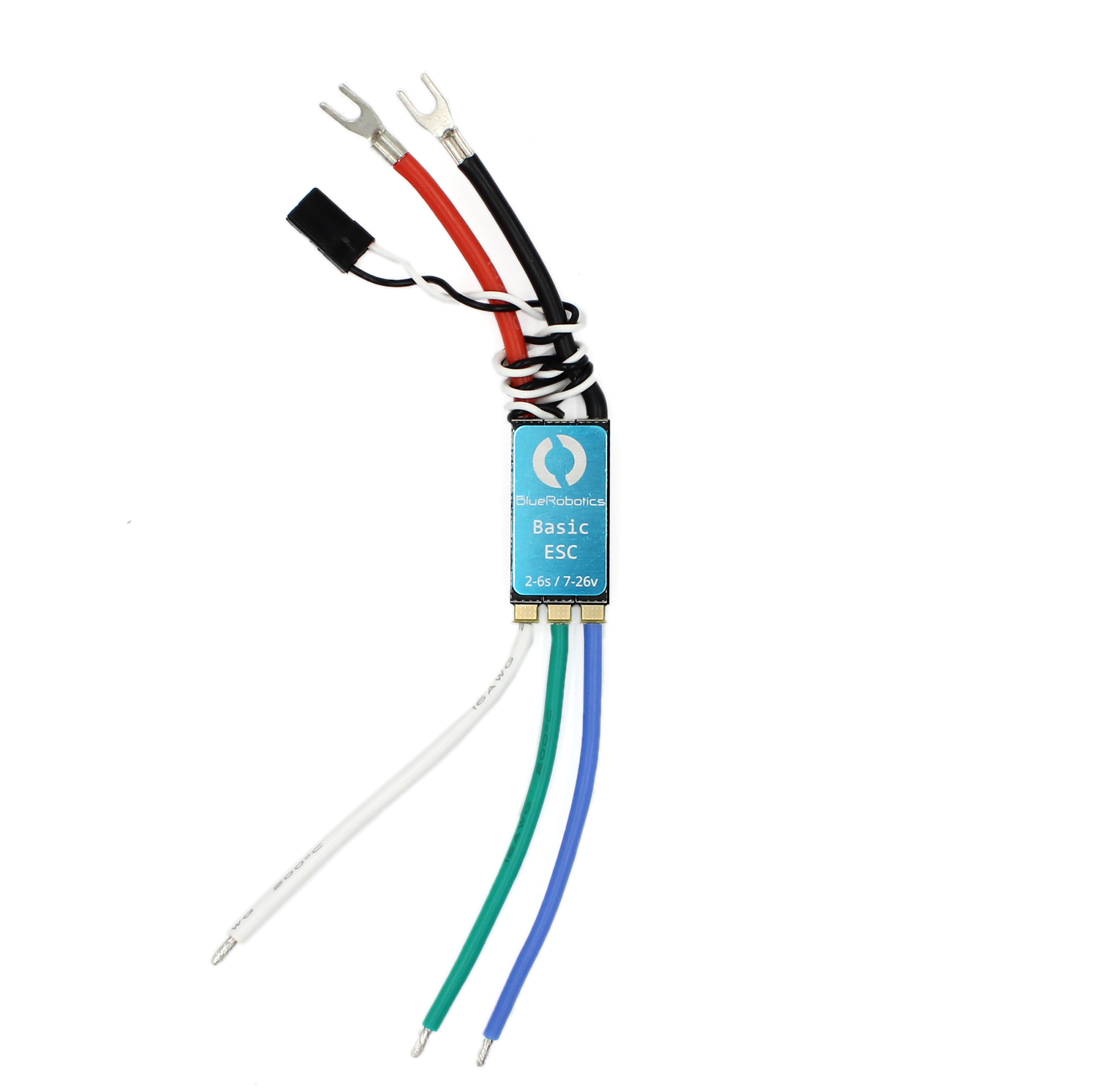
The Basic Motor Electronic Speed Controller (ESC) by Blue Robotics is a compact and efficient device designed to regulate the speed, direction, and braking of electric motors. By varying the voltage and current supplied to the motor, this ESC enables precise control, making it an essential component in applications such as drones, remote-controlled (RC) vehicles, robotics, and other motor-driven systems. Its robust design ensures reliable performance in demanding environments.
Explore Projects Built with Basic Motor ESC


Explore Projects Built with Basic Motor ESC
Common Applications
- Drones and quadcopters for motor speed control
- Remote-controlled cars, boats, and aircraft
- Robotics projects requiring precise motor control
- Industrial automation systems
- Electric propulsion systems for small vehicles
Technical Specifications
Key Technical Details
| Parameter | Value |
|---|---|
| Input Voltage Range | 6V to 30V (2S to 6S LiPo) |
| Continuous Current | 30A |
| Peak Current | 40A (for 10 seconds) |
| Supported Motor Types | Brushless DC (BLDC) motors |
| Signal Input Type | PWM (Pulse Width Modulation) |
| PWM Signal Range | 1000µs to 2000µs |
| BEC Output | 5V, 2A |
| Dimensions | 45mm x 25mm x 10mm |
| Weight | 20g |
| Operating Temperature | -10°C to 60°C |
Pin Configuration and Descriptions
The Basic Motor ESC has three main connection interfaces: Input Power, Motor Output, and Signal Input.
Input Power and Motor Output
| Pin Name | Description |
|---|---|
| + (Red Wire) | Positive input voltage (connect to battery +) |
| - (Black Wire) | Ground (connect to battery -) |
| A (Motor Wire) | Connect to one phase of the brushless motor |
| B (Motor Wire) | Connect to another phase of the brushless motor |
| C (Motor Wire) | Connect to the third phase of the brushless motor |
Signal Input
| Pin Name | Description |
|---|---|
| Signal (White) | PWM signal input for speed control |
| +5V (Red) | 5V output from the ESC's BEC (optional use) |
| GND (Black) | Ground reference for the signal input |
Usage Instructions
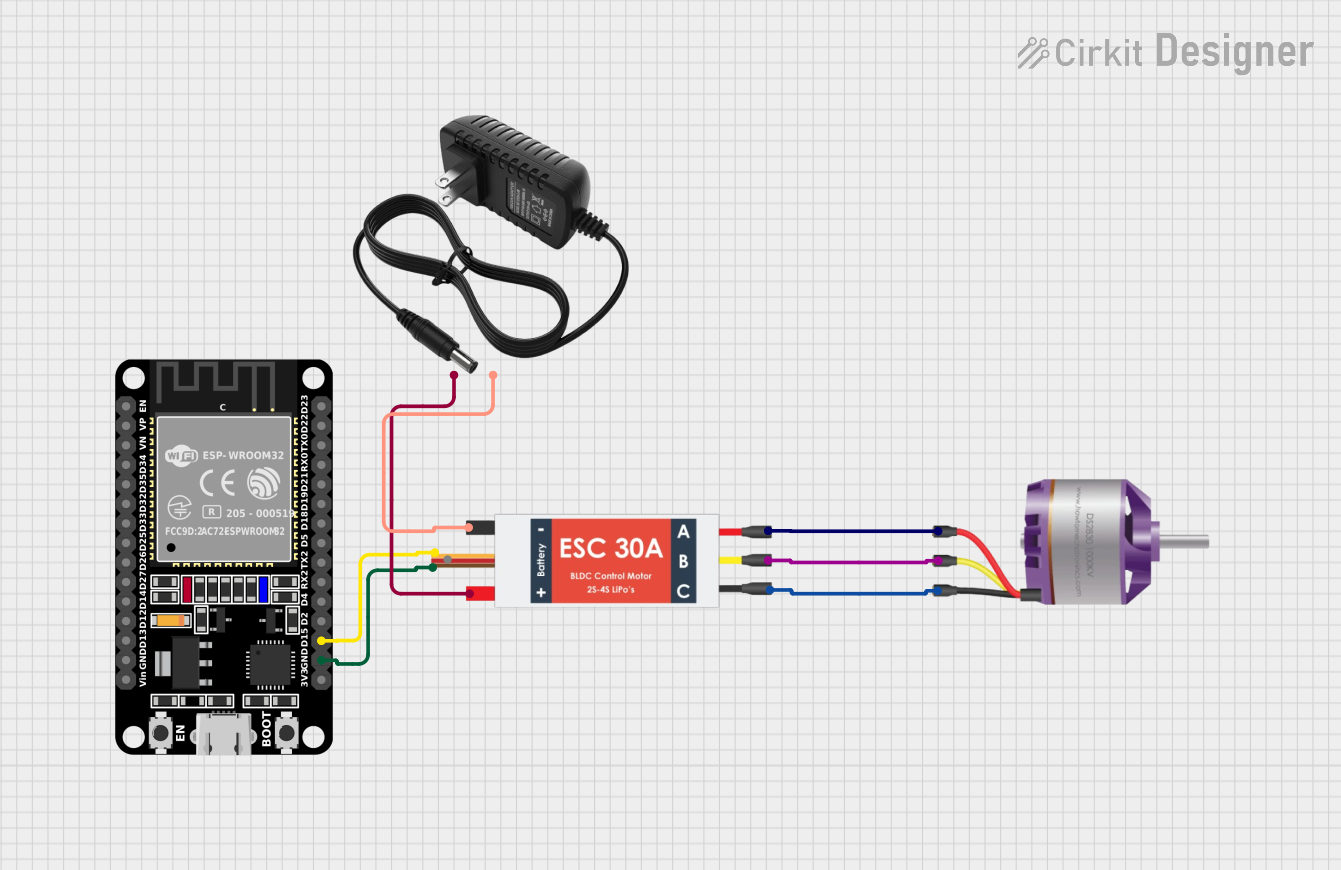
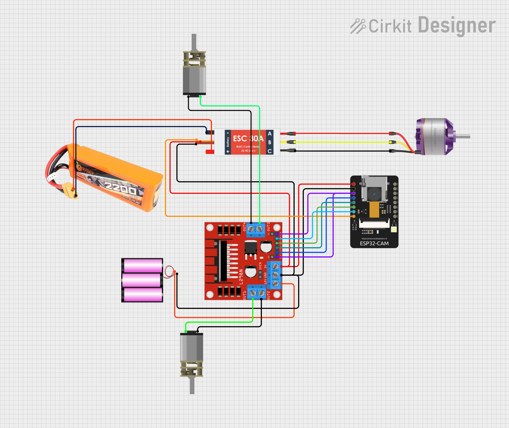
How to Use the Basic Motor ESC in a Circuit
Connect the Power Supply:
- Attach the red wire (
+) to the positive terminal of your battery. - Attach the black wire (
-) to the negative terminal of your battery. - Ensure the input voltage is within the specified range (6V to 30V).
- Attach the red wire (
Connect the Motor:
- Connect the three motor wires (
A,B,C) to the corresponding phases of your brushless motor. - If the motor spins in the wrong direction, swap any two of the motor wires.
- Connect the three motor wires (
Connect the Signal Input:
- Connect the white wire (
Signal) to the PWM output pin of your microcontroller or receiver. - Connect the black wire (
GND) to the ground of your microcontroller or receiver. - Optionally, use the red wire (
+5V) to power your microcontroller or receiver if needed.
- Connect the white wire (
Calibrate the ESC (if required):
- Power on the ESC while holding the throttle at maximum.
- Wait for the calibration tones, then move the throttle to the minimum position.
- Wait for the confirmation tones to complete the calibration.
Test the Setup:
- Gradually increase the throttle signal to test motor speed control.
- Ensure the motor operates smoothly without unusual noises or vibrations.
Important Considerations and Best Practices
- Cooling: Ensure adequate airflow or cooling to prevent the ESC from overheating during operation.
- Signal Range: Verify that the PWM signal range (1000µs to 2000µs) matches your microcontroller or receiver.
- Battery Compatibility: Use a battery within the specified voltage range (2S to 6S LiPo).
- Motor Compatibility: Only use the ESC with brushless DC motors.
- Safety: Always disconnect the power supply when making wiring changes.
Example Code for Arduino UNO
The following example demonstrates how to control the Basic Motor ESC using an Arduino UNO:
#include <Servo.h> // Include the Servo library for PWM signal generation

Servo esc; // Create a Servo object to control the ESC

void setup() {
  esc.attach(9); // Attach the ESC signal wire to pin 9
  esc.writeMicroseconds(1000); // Set the ESC to minimum throttle
  delay(2000); // Wait for 2 seconds to initialize the ESC
}

void loop() {
  // Gradually increase throttle from minimum to maximum
  for (int throttle = 1000; throttle <= 2000; throttle += 10) {
    esc.writeMicroseconds(throttle); // Send PWM signal to the ESC
    delay(20); // Wait for 20ms between steps
  }

  delay(2000); // Hold at maximum throttle for 2 seconds

  // Gradually decrease throttle from maximum to minimum
  for (int throttle = 2000; throttle >= 1000; throttle -= 10) {
    esc.writeMicroseconds(throttle); // Send PWM signal to the ESC
    delay(20); // Wait for 20ms between steps
  }

  delay(2000); // Hold at minimum throttle for 2 seconds
}
Troubleshooting and FAQs
Common Issues and Solutions
Motor Does Not Spin:
- Cause: Incorrect wiring or no PWM signal.
- Solution: Verify all connections, ensure the ESC is receiving a valid PWM signal, and check the battery voltage.
Motor Spins in the Wrong Direction:
- Cause: Incorrect motor phase wiring.
- Solution: Swap any two of the motor wires (
A,B, orC).
ESC Overheats:
- Cause: Excessive current draw or poor cooling.
- Solution: Ensure the motor is not overloaded and provide adequate airflow or a heatsink.
No Response from ESC:
- Cause: Calibration not performed or incorrect signal range.
- Solution: Perform the ESC calibration process and verify the PWM signal range (1000µs to 2000µs).
Motor Stutters or Vibrates:
- Cause: Poor connections or incompatible motor.
- Solution: Check all connections and ensure the motor is a brushless DC type.
FAQs
Q: Can I use this ESC with a brushed motor?
A: No, this ESC is designed specifically for brushless DC motors.Q: What happens if I exceed the input voltage range?
A: Exceeding the voltage range may damage the ESC permanently. Always use a compatible battery.Q: Can I power my Arduino UNO using the ESC's BEC output?
A: Yes, the ESC's 5V BEC output can power your Arduino UNO, but ensure the total current draw does not exceed 2A.Q: How do I stop the motor quickly?
A: Send a PWM signal corresponding to the minimum throttle (1000µs) to stop the motor.
This documentation provides a comprehensive guide to using the Basic Motor ESC by Blue Robotics. Follow the instructions and best practices to ensure optimal performance and longevity of your ESC.