How to Use Battery Indicator: Examples, Pinouts, and Specs
Introduction
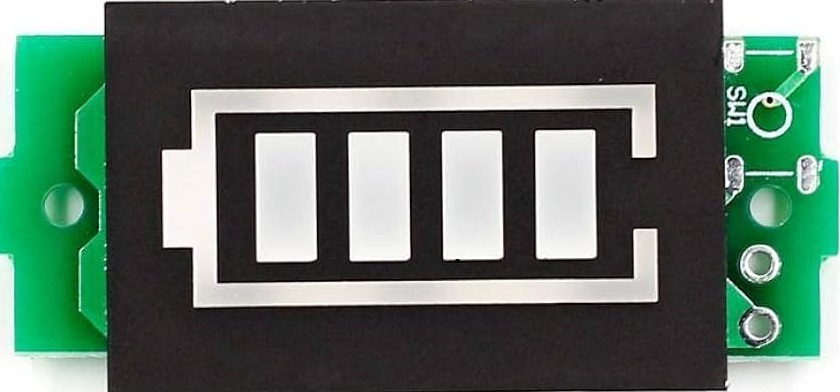
A battery indicator is an essential electronic component that provides a visual representation of a battery's charge status. It is commonly used in portable devices, power banks, electric vehicles, and other battery-powered systems to inform users about the remaining battery life. This helps in preventing unexpected power loss and in planning recharging cycles.
Explore Projects Built with Battery Indicator
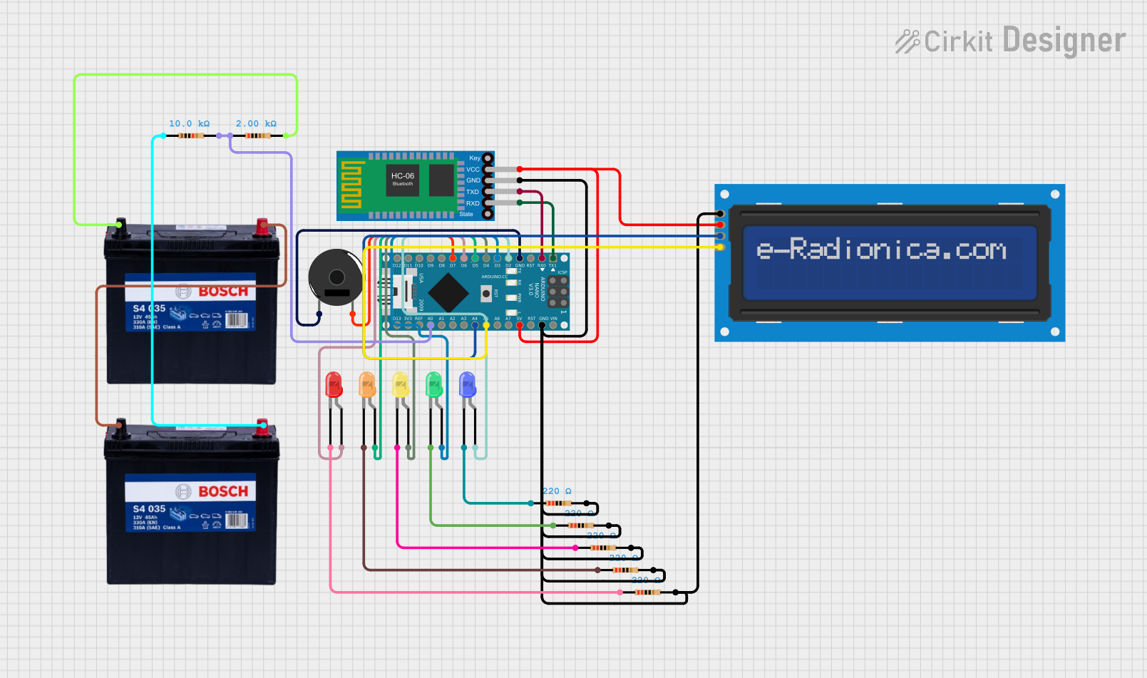

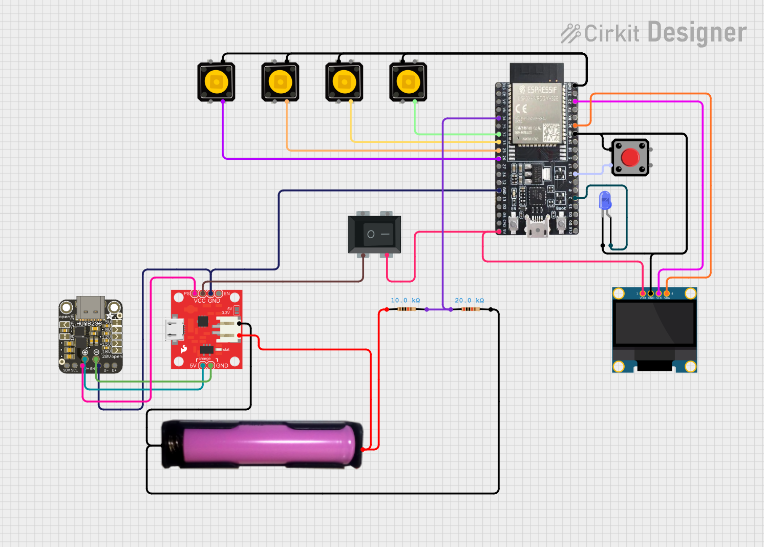
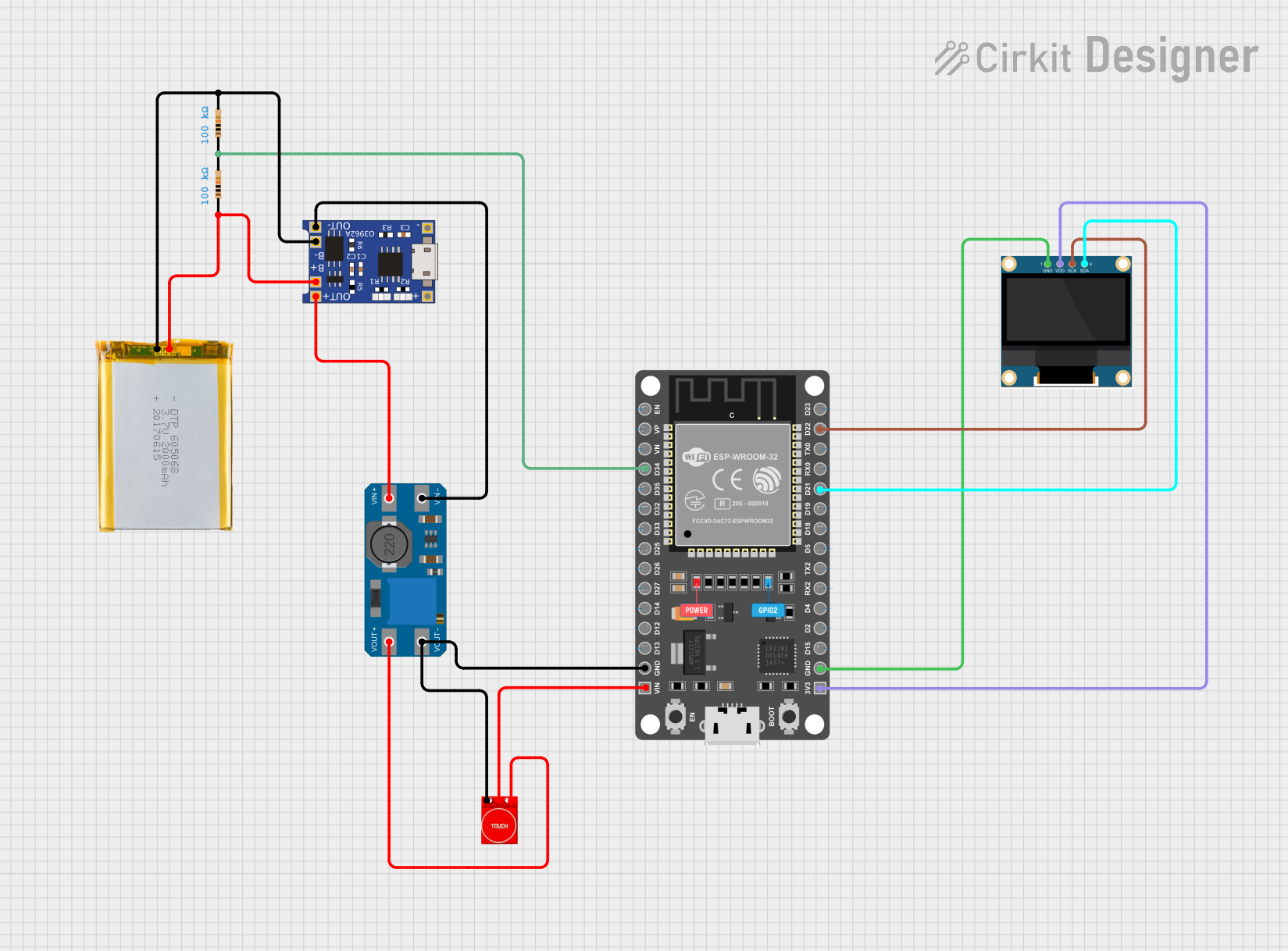
Explore Projects Built with Battery Indicator
Technical Specifications
Key Technical Details
- Operating Voltage Range: Typically 2.7V to 4.2V for single-cell Li-ion batteries.
- Current Consumption: Varies with model, often in the microamp range to preserve battery life.
- Accuracy: Dependent on the design, can range from simple LED indicators to precise digital readouts.
- Display Type: LED, LCD, or OLED, with multiple segments or bars indicating charge levels.
Pin Configuration and Descriptions
| Pin Number | Description | Notes |
|---|---|---|
| 1 | VBAT (Battery Voltage Input) | Connect to the positive terminal of the battery. |
| 2 | GND (Ground) | Connect to the negative terminal of the battery. |
| 3 | SENSE (Voltage Sense Input) | Optional, for more accurate readings. |
| 4 | ENABLE (Display Enable) | Active high to turn on the display, can be tied to VBAT if always on. |
| 5 | NC (No Connection) | Not connected or used in the circuit. |
Usage Instructions
How to Use the Component in a Circuit
- Connect the Battery: Attach the positive terminal of the battery to the VBAT pin and the negative terminal to the GND pin.
- Enable the Display: If the battery indicator has an ENABLE pin, connect it to a high logic level to turn on the display. This can be directly to VBAT if the display should always be on.
- Optional Sense Pin: If available, connect the SENSE pin to a point in the circuit where battery voltage can be accurately measured.
- Mounting the Display: Position the battery indicator where it can be easily seen by the user.
Important Considerations and Best Practices
- Voltage Compatibility: Ensure the battery voltage is within the operating range of the battery indicator.
- Power Consumption: Choose a battery indicator with low power consumption to minimize the impact on battery life.
- Calibration: Some battery indicators may require calibration for accurate readings.
- Environmental Factors: Temperature and aging can affect battery voltage; consider these factors when interpreting the indicator.
Troubleshooting and FAQs
Common Issues
- Inaccurate Readings: Ensure the battery indicator is correctly calibrated and that the SENSE pin is connected if available.
- No Display: Check the connections to VBAT and GND, and ensure the ENABLE pin is receiving a high logic level if applicable.
- Intermittent Display: Verify that all connections are secure and that there is no intermittent contact.
Solutions and Tips for Troubleshooting
- Calibration: Follow the manufacturer's instructions to calibrate the battery indicator for precise readings.
- Connection Check: Recheck all connections, including solder joints, for continuity.
- Battery Health: Remember that an old or damaged battery may not provide accurate voltage levels, affecting the indicator's performance.
FAQs
Q: Can I use the battery indicator for different types of batteries? A: Yes, but ensure the voltage range is compatible and recalibrate if necessary.
Q: How do I know if my battery indicator is accurate? A: Compare its readings with a known good voltmeter or reference battery.
Q: Does the battery indicator consume battery power? A: Yes, but it is typically designed to consume very little power.
Example Code for Arduino UNO
If you're using a digital battery indicator with an Arduino UNO, you can read the battery level and display it on the serial monitor.
// Define the analog pin connected to the battery indicator
const int batteryPin = A0;

void setup() {
  // Begin serial communication at a baud rate of 9600
  Serial.begin(9600);
}

void loop() {
  // Read the analog value from the battery indicator
  int sensorValue = analogRead(batteryPin);
  // Convert the analog reading (which goes from 0 - 1023) to a voltage (0 - 5V)
  float voltage = sensorValue * (5.0 / 1023.0);
  // Print out the voltage to the serial monitor
  Serial.print("Battery Voltage: ");
  Serial.println(voltage);
  // Wait for a bit before reading again
  delay(1000);
}
Remember to adjust the voltage calculation if you're using a voltage divider or if your battery's voltage range exceeds 5V.