Cirkit Designer Logo
Cirkit Designer
Your all-in-one circuit design IDE
Home / 
Component Documentation

How to Use ИПР-513-3АМ: Examples, Pinouts, and Specs

Image of ИПР-513-3АМ
Cirkit Designer LogoDesign with ИПР-513-3АМ in Cirkit Designer

Introduction

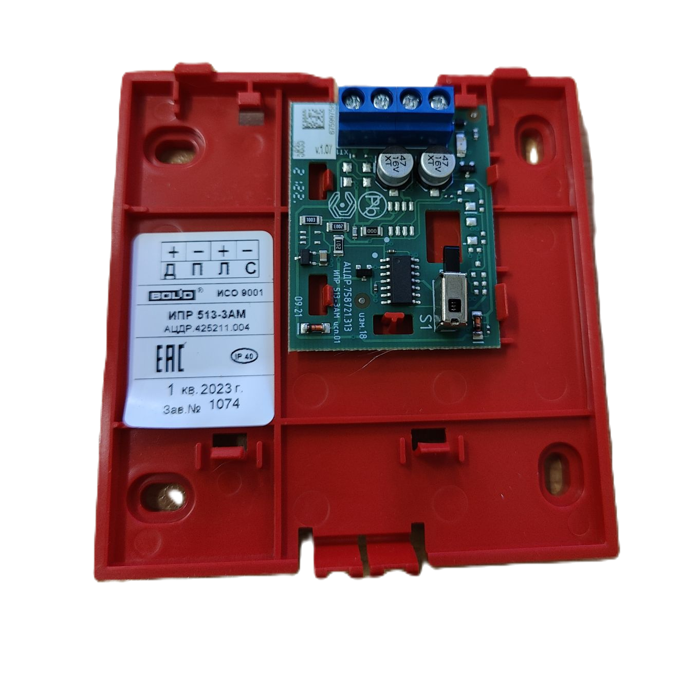
The ИПР-513-3АМ, manufactured by Bolid, is a versatile integrated circuit designed for signal processing and control applications. Known for its reliability and efficiency, this component is widely used in industrial automation, security systems, and other electronic systems requiring precise signal management. Its robust design ensures stable performance even in demanding environments.

Explore Projects Built with ИПР-513-3АМ

Use Cirkit Designer to design, explore, and prototype these projects online. Some projects support real-time simulation. Click "Open Project" to start designing instantly!
4-Pin Connector Circuit for Edge Detection
Image of 4pin: A project utilizing ИПР-513-3АМ in a practical application
This circuit appears to be a simple interconnection of pins and points, with a 4-pin component serving as a central hub. The red and black pins of the 4-pin component are connected to various other pins and edge components, forming a basic network of connections without any active components or microcontroller logic.
Cirkit Designer LogoOpen Project in Cirkit Designer
Arduino Mega 2560 Based Security System with Fingerprint Authentication and SMS Alerts
Image of Door security system: A project utilizing ИПР-513-3АМ in a practical application
This circuit features an Arduino Mega 2560 microcontroller interfaced with a SIM800L GSM module, two fingerprint scanners, an I2C LCD display, an IR sensor, and a piezo buzzer. Power management is handled by a PowerBoost 1000 Basic Pad USB, a TP4056 charging module, and a Li-ion 18650 battery, with an option to use a Mini AC-DC 110V-230V to 5V 700mA module for direct power supply. The primary functionality appears to be a security system with GSM communication capabilities, biometric access control, and visual/audible feedback.
Cirkit Designer LogoOpen Project in Cirkit Designer
NFC-Enabled Access Control System with Time Logging
Image of doorlock: A project utilizing ИПР-513-3АМ in a practical application
This circuit is designed for access control with time tracking capabilities. It features an NFC/RFID reader for authentication, an RTC module (DS3231) for real-time clock functionality, and an OLED display for user interaction. A 12V relay controls a magnetic lock, which is activated upon successful NFC/RFID authentication, and a button switch is likely used for manual operation or input. The T8_S3 microcontroller serves as the central processing unit, interfacing with the NFC/RFID reader, RTC, OLED, and relay to manage the access control logic.
Cirkit Designer LogoOpen Project in Cirkit Designer
Battery-Powered Laser Emitter with Solar Charging and LED Indicator
Image of rx: A project utilizing ИПР-513-3АМ in a practical application
This circuit is a solar-powered laser emitter system with an LED indicator. The solar panel charges a 18650 battery via a TP4056 charging module, and a push button controls the activation of the laser emitter and the LED through a MOSFET switch.
Cirkit Designer LogoOpen Project in Cirkit Designer

Explore Projects Built with ИПР-513-3АМ

Use Cirkit Designer to design, explore, and prototype these projects online. Some projects support real-time simulation. Click "Open Project" to start designing instantly!
Image of 4pin: A project utilizing ИПР-513-3АМ in a practical application
4-Pin Connector Circuit for Edge Detection
This circuit appears to be a simple interconnection of pins and points, with a 4-pin component serving as a central hub. The red and black pins of the 4-pin component are connected to various other pins and edge components, forming a basic network of connections without any active components or microcontroller logic.
Cirkit Designer LogoOpen Project in Cirkit Designer
Image of Door security system: A project utilizing ИПР-513-3АМ in a practical application
Arduino Mega 2560 Based Security System with Fingerprint Authentication and SMS Alerts
This circuit features an Arduino Mega 2560 microcontroller interfaced with a SIM800L GSM module, two fingerprint scanners, an I2C LCD display, an IR sensor, and a piezo buzzer. Power management is handled by a PowerBoost 1000 Basic Pad USB, a TP4056 charging module, and a Li-ion 18650 battery, with an option to use a Mini AC-DC 110V-230V to 5V 700mA module for direct power supply. The primary functionality appears to be a security system with GSM communication capabilities, biometric access control, and visual/audible feedback.
Cirkit Designer LogoOpen Project in Cirkit Designer
Image of doorlock: A project utilizing ИПР-513-3АМ in a practical application
NFC-Enabled Access Control System with Time Logging
This circuit is designed for access control with time tracking capabilities. It features an NFC/RFID reader for authentication, an RTC module (DS3231) for real-time clock functionality, and an OLED display for user interaction. A 12V relay controls a magnetic lock, which is activated upon successful NFC/RFID authentication, and a button switch is likely used for manual operation or input. The T8_S3 microcontroller serves as the central processing unit, interfacing with the NFC/RFID reader, RTC, OLED, and relay to manage the access control logic.
Cirkit Designer LogoOpen Project in Cirkit Designer
Image of rx: A project utilizing ИПР-513-3АМ in a practical application
Battery-Powered Laser Emitter with Solar Charging and LED Indicator
This circuit is a solar-powered laser emitter system with an LED indicator. The solar panel charges a 18650 battery via a TP4056 charging module, and a push button controls the activation of the laser emitter and the LED through a MOSFET switch.
Cirkit Designer LogoOpen Project in Cirkit Designer

Common Applications

  • Industrial automation systems
  • Security and alarm systems
  • Signal processing in control circuits
  • Monitoring and diagnostic equipment
  • General-purpose electronic control systems

Technical Specifications

Key Technical Details

Parameter Value
Supply Voltage (Vcc) 5V to 15V
Operating Current ≤ 20 mA
Signal Input Voltage 0V to Vcc
Output Voltage Range 0V to Vcc
Operating Temperature -40°C to +85°C
Package Type DIP-8 (Dual Inline Package)

Pin Configuration and Descriptions

Pin Number Pin Name Description
1 Vcc Positive power supply input
2 IN1 Signal input 1
3 IN2 Signal input 2
4 GND Ground (0V reference)
5 OUT1 Signal output 1
6 OUT2 Signal output 2
7 NC Not connected (leave unconnected or grounded)
8 Vref Reference voltage input for signal processing

Usage Instructions

How to Use the ИПР-513-3АМ in a Circuit

  1. Power Supply: Connect the Vcc pin to a stable DC power source within the range of 5V to 15V. Ensure the GND pin is connected to the circuit ground.
  2. Signal Inputs: Apply input signals to the IN1 and IN2 pins. The input voltage should not exceed the supply voltage (Vcc).
  3. Signal Outputs: The processed signals will be available at the OUT1 and OUT2 pins. These outputs can be connected to other components or systems for further processing or control.
  4. Reference Voltage: If required, provide a reference voltage to the Vref pin to adjust the signal processing behavior. This is optional and depends on the specific application.

Important Considerations

  • Decoupling Capacitors: Place a 0.1 µF ceramic capacitor close to the Vcc and GND pins to filter out noise and ensure stable operation.
  • Input Protection: Use resistors or diodes to protect the input pins from voltage spikes or overvoltage conditions.
  • Thermal Management: Ensure adequate ventilation or heat dissipation if the component operates in high-temperature environments.

Example: Connecting to an Arduino UNO

The ИПР-513-3АМ can be interfaced with an Arduino UNO for signal processing tasks. Below is an example of how to connect and use it:

Circuit Connections

  • Connect the Vcc pin of the ИПР-513-3АМ to the 5V pin of the Arduino.
  • Connect the GND pin of the ИПР-513-3АМ to the GND pin of the Arduino.
  • Connect IN1 to an Arduino digital pin (e.g., D2) for input signal.
  • Connect OUT1 to another Arduino digital pin (e.g., D3) to read the processed signal.

Arduino Code Example

// Example code for interfacing ИПР-513-3АМ with Arduino UNO

const int inputPin = 2;  // Arduino pin connected to ИПР-513-3АМ IN1
const int outputPin = 3; // Arduino pin connected to ИПР-513-3АМ OUT1

void setup() {
  pinMode(inputPin, INPUT);  // Set inputPin as input
  pinMode(outputPin, OUTPUT); // Set outputPin as output
  Serial.begin(9600);        // Initialize serial communication
}

void loop() {
  int inputSignal = digitalRead(inputPin); // Read signal from ИПР-513-3АМ IN1
  digitalWrite(outputPin, inputSignal);    // Output the same signal to OUT1

  // Print the input signal to the Serial Monitor for debugging
  Serial.print("Input Signal: ");
  Serial.println(inputSignal);

  delay(100); // Small delay for stability
}

Best Practices

  • Always verify the input and output voltage levels to prevent damage to the component.
  • Use proper grounding techniques to minimize noise and interference in the circuit.
  • Test the circuit on a breadboard before finalizing the design.

Troubleshooting and FAQs

Common Issues and Solutions

Issue Possible Cause Solution
No output signal Incorrect power supply connection Verify Vcc and GND connections
Output signal is distorted Noise or unstable power supply Add decoupling capacitors near Vcc and GND
Component overheating Excessive current draw Check for short circuits or reduce load
No response to input signals Input voltage out of range Ensure input voltage is within 0V to Vcc

FAQs

Q: Can the ИПР-513-3АМ handle AC signals?
A: No, the ИПР-513-3АМ is designed for DC signal processing. Use additional circuitry to convert AC signals to DC if needed.

Q: What is the purpose of the Vref pin?
A: The Vref pin allows you to set a reference voltage for signal processing, which can be useful for applications requiring specific thresholds or offsets.

Q: Can I leave unused pins unconnected?
A: Yes, unused pins such as NC (Not Connected) can be left unconnected or tied to ground for stability.

By following this documentation, users can effectively integrate the ИПР-513-3АМ into their electronic projects and troubleshoot common issues with ease.