Cirkit Designer Logo
Cirkit Designer
Your all-in-one circuit design IDE
Home / 
Component Documentation

How to Use ESP32 - 38 pins Expansion Board: Examples, Pinouts, and Specs
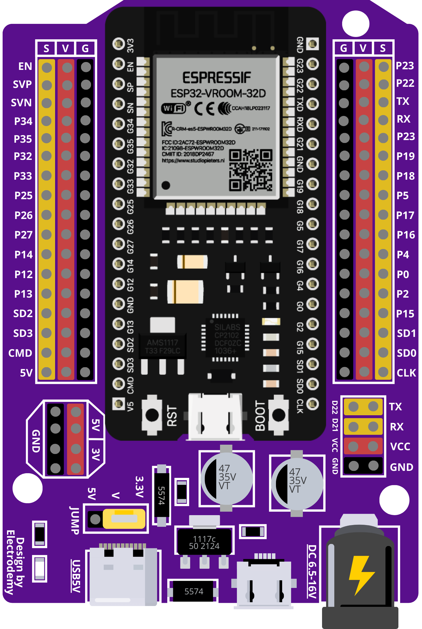
Image of ESP32 - 38 pins Expansion Board
Cirkit Designer LogoDesign with ESP32 - 38 pins Expansion Board in Cirkit Designer

Introduction

The ESP32 - 38 Pins Expansion Board is a versatile add-on for the ESP32 microcontroller. It extends the number of available GPIO pins, allowing users to connect more peripherals and sensors. This board is ideal for complex projects that require multiple I/O connections, such as home automation systems, IoT devices, and robotics.

Explore Projects Built with ESP32 - 38 pins Expansion Board
Use Cirkit Designer to design, explore, and prototype these projects online. Some projects support real-time simulation. Click "Open Project" to start designing instantly!
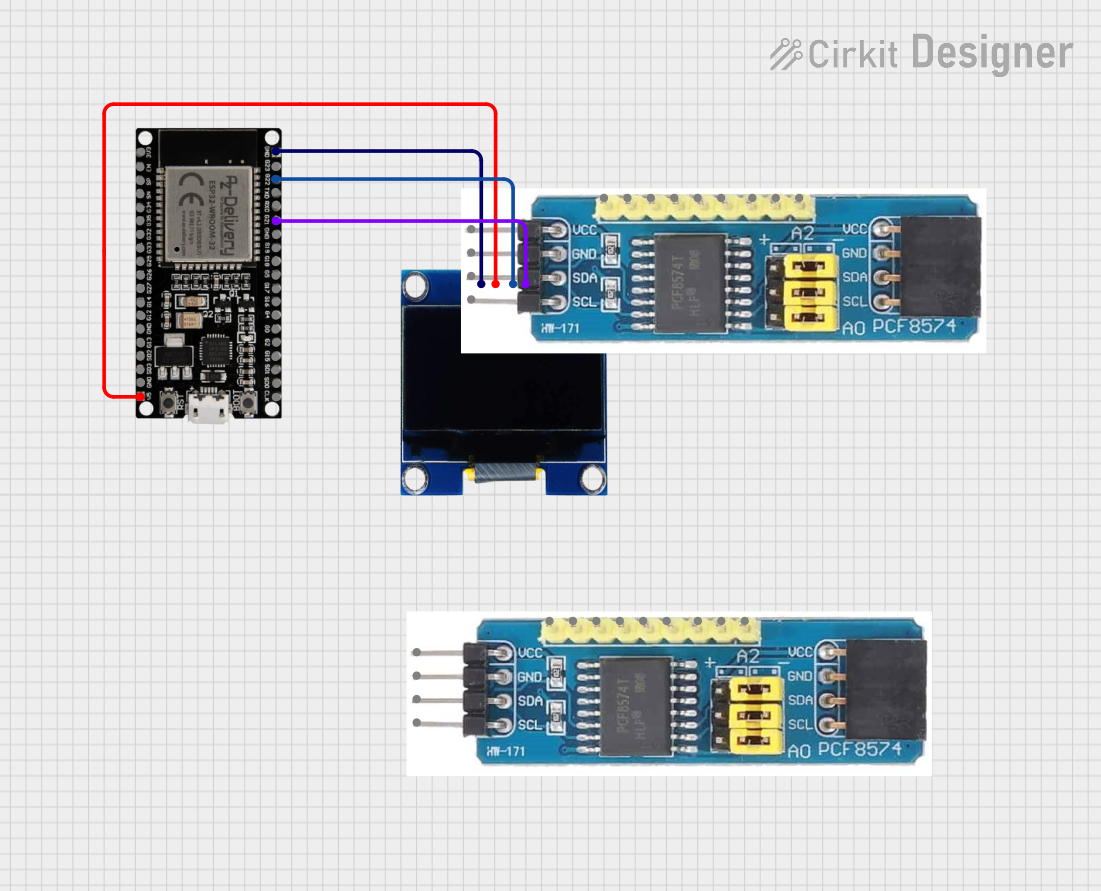
ESP32-Based OLED Display Interface
Image of d: A project utilizing ESP32 - 38 pins Expansion Board in a practical application
This circuit features an ESP32 microcontroller connected to an OLED 1.3" display. The ESP32's GPIO pins 21 and 22 are used for I2C communication (SDA and SCL respectively) with the OLED display. The display is powered by the 5V output from the ESP32, and both devices share a common ground.
Cirkit Designer LogoOpen Project in Cirkit Designer
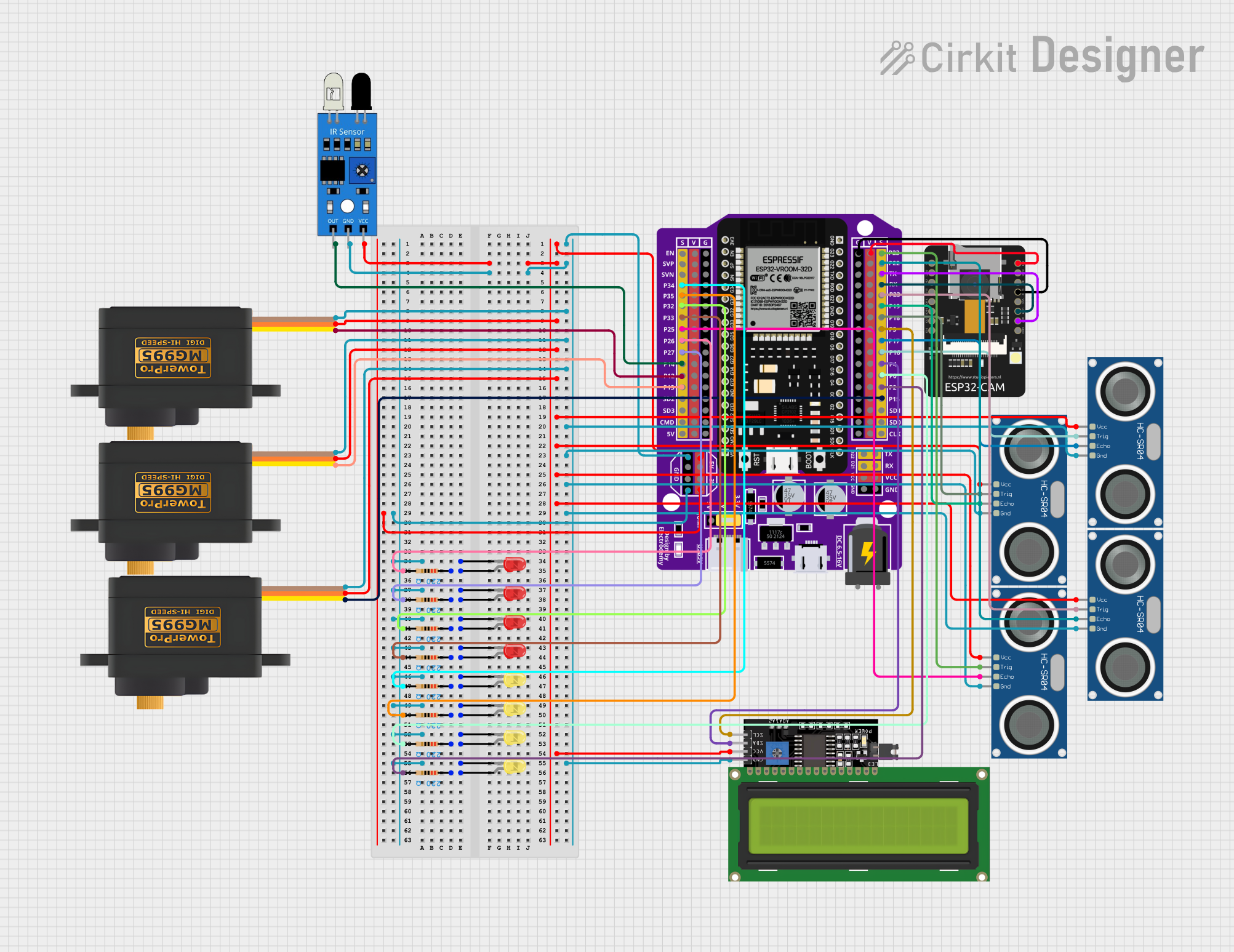
ESP32-Based Obstacle Detection and Display System with Servo Control
Image of xyhaeee: A project utilizing ESP32 - 38 pins Expansion Board in a practical application
This circuit features an ESP32 microcontroller board as the central processing unit, interfaced with multiple sensors and actuators. It includes IR and ultrasonic sensors for distance or obstacle detection, servomotors for movement control, and an ESP32-CAM module for image capture. The circuit also incorporates LEDs with current-limiting resistors for status indication and an I2C LCD display for outputting information or readings.
Cirkit Designer LogoOpen Project in Cirkit Designer
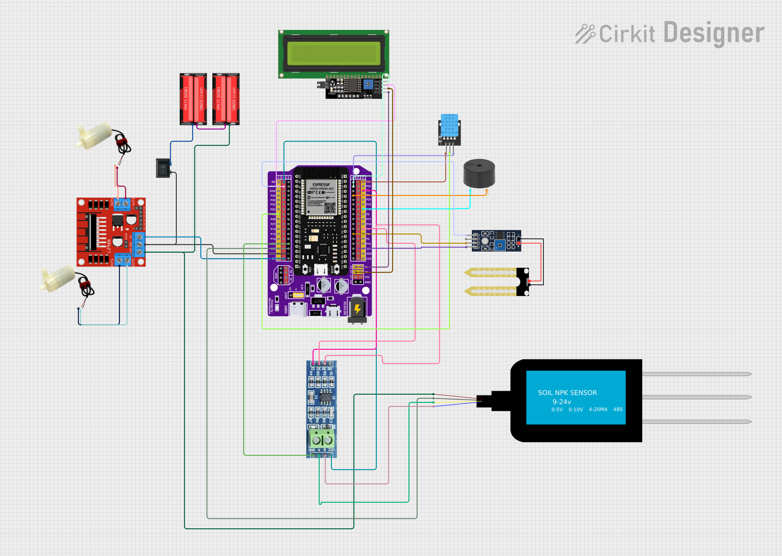
ESP32-Based Smart Irrigation and Environmental Monitoring System
Image of fyp: A project utilizing ESP32 - 38 pins Expansion Board in a practical application
This circuit features an ESP32 microcontroller as the central processing unit, interfaced with various sensors and actuators. It includes a humidity sensor (YL-69), a temperature and humidity sensor (DHT11), a buzzer, an RS485 transceiver for serial communication, and an LCD display for user interface. The circuit also controls two 5V mini water pumps via an L298N motor driver, powered by a series connection of two 18650 Li-Ion batteries, with a rocker switch for power control. Additionally, it integrates an NPK soil sensor for measuring soil nutrients.
Cirkit Designer LogoOpen Project in Cirkit Designer
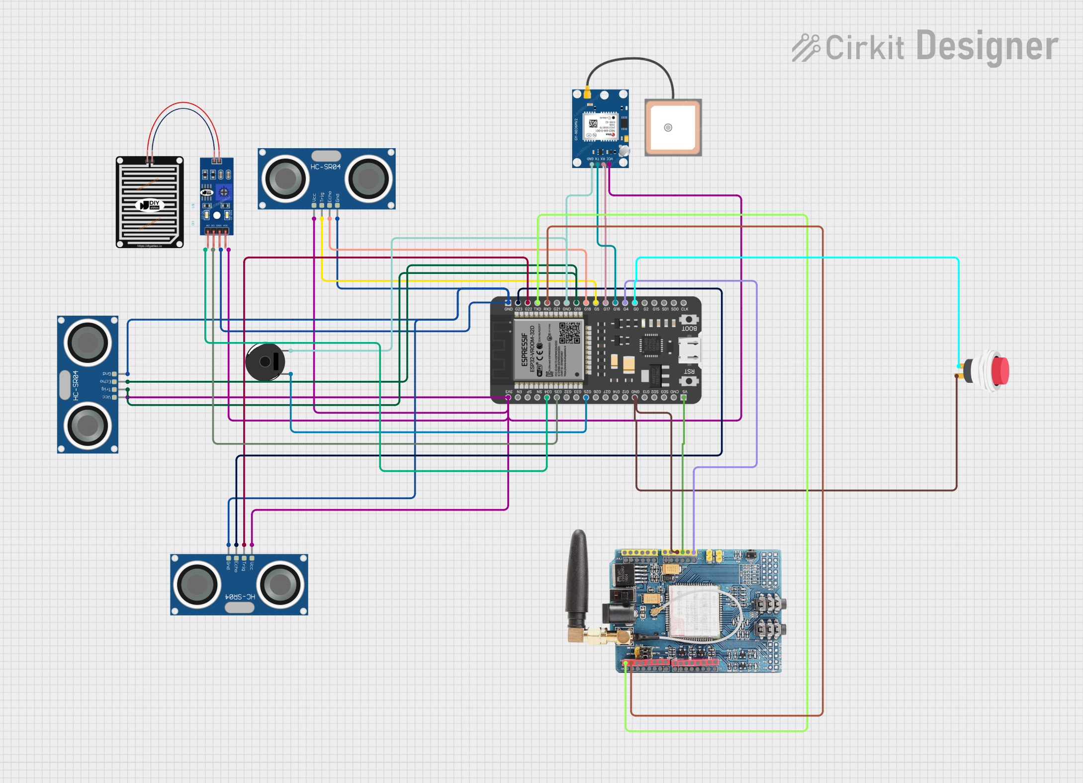
ESP32-Based Environmental Monitoring System with Ultrasonic, GPS, GSM, and Rain Sensor
Image of SMART BLIND STICK CONNECTION: A project utilizing ESP32 - 38 pins Expansion Board in a practical application
This circuit features an ESP32 microcontroller connected to multiple sensors and modules for environmental data collection and communication. It includes three HC-SR04 ultrasonic sensors for distance measurement, a rain sensor for detecting precipitation, a GPS NEO 6M module for location tracking, and a GSM SIM900 module for cellular communication. Additionally, there is a piezo buzzer for audio feedback and a push switch for user input, all sharing a common ground with the ESP32.
Cirkit Designer LogoOpen Project in Cirkit Designer

Explore Projects Built with ESP32 - 38 pins Expansion Board

Use Cirkit Designer to design, explore, and prototype these projects online. Some projects support real-time simulation. Click "Open Project" to start designing instantly!
Image of d: A project utilizing ESP32 - 38 pins Expansion Board in a practical application
ESP32-Based OLED Display Interface
This circuit features an ESP32 microcontroller connected to an OLED 1.3" display. The ESP32's GPIO pins 21 and 22 are used for I2C communication (SDA and SCL respectively) with the OLED display. The display is powered by the 5V output from the ESP32, and both devices share a common ground.
Cirkit Designer LogoOpen Project in Cirkit Designer
Image of xyhaeee: A project utilizing ESP32 - 38 pins Expansion Board in a practical application
ESP32-Based Obstacle Detection and Display System with Servo Control
This circuit features an ESP32 microcontroller board as the central processing unit, interfaced with multiple sensors and actuators. It includes IR and ultrasonic sensors for distance or obstacle detection, servomotors for movement control, and an ESP32-CAM module for image capture. The circuit also incorporates LEDs with current-limiting resistors for status indication and an I2C LCD display for outputting information or readings.
Cirkit Designer LogoOpen Project in Cirkit Designer
Image of fyp: A project utilizing ESP32 - 38 pins Expansion Board in a practical application
ESP32-Based Smart Irrigation and Environmental Monitoring System
This circuit features an ESP32 microcontroller as the central processing unit, interfaced with various sensors and actuators. It includes a humidity sensor (YL-69), a temperature and humidity sensor (DHT11), a buzzer, an RS485 transceiver for serial communication, and an LCD display for user interface. The circuit also controls two 5V mini water pumps via an L298N motor driver, powered by a series connection of two 18650 Li-Ion batteries, with a rocker switch for power control. Additionally, it integrates an NPK soil sensor for measuring soil nutrients.
Cirkit Designer LogoOpen Project in Cirkit Designer
Image of SMART BLIND STICK CONNECTION: A project utilizing ESP32 - 38 pins Expansion Board in a practical application
ESP32-Based Environmental Monitoring System with Ultrasonic, GPS, GSM, and Rain Sensor
This circuit features an ESP32 microcontroller connected to multiple sensors and modules for environmental data collection and communication. It includes three HC-SR04 ultrasonic sensors for distance measurement, a rain sensor for detecting precipitation, a GPS NEO 6M module for location tracking, and a GSM SIM900 module for cellular communication. Additionally, there is a piezo buzzer for audio feedback and a push switch for user input, all sharing a common ground with the ESP32.
Cirkit Designer LogoOpen Project in Cirkit Designer

Common Applications and Use Cases

  • IoT (Internet of Things) devices
  • Home automation
  • Robotics
  • Complex projects requiring multiple sensor integrations
  • Prototyping and educational purposes

Technical Specifications

Key Technical Details

  • Compatible with ESP32 microcontroller
  • Number of Expansion Pins: 38
  • Voltage Rating: 3.3V (Do not exceed the voltage rating as it can damage the board)
  • Current Rating: Depends on the ESP32 module used

Pin Configuration and Descriptions

Pin Number Function Description
1-16 GPIO Expansion General Purpose Input/Output pins
17-21 ADC Channels Analog to Digital Converter channels
22-25 SPI Interface Serial Peripheral Interface for communication
26-29 I2C Interface Inter-Integrated Circuit for communication
30-33 UART Interface Universal Asynchronous Receiver-Transmitter interface
34-38 Extra Functions Reserved for future use or specific applications

Usage Instructions

How to Use the Component in a Circuit

  1. Mounting the ESP32: Securely mount the ESP32 onto the expansion board ensuring proper alignment of pins.
  2. Power Supply: Connect a 3.3V power supply to the designated VCC and GND pins on the expansion board.
  3. Connecting Peripherals: Attach sensors, actuators, or other peripherals to the expansion GPIO pins.
  4. Programming: Use the ESP32's programming interface to upload your code.

Important Considerations and Best Practices

  • Voltage Levels: Ensure that all peripherals are compatible with the 3.3V logic levels of the ESP32.
  • Current Draw: Be mindful of the total current draw from the GPIO pins to avoid damaging the ESP32.
  • ESD Precautions: Always handle the board with proper electrostatic discharge (ESD) precautions.
  • Firmware: Keep the ESP32 firmware updated to the latest version for optimal performance and security.

Troubleshooting and FAQs

Common Issues Users Might Face

  • Board Not Recognized: Ensure that the ESP32 is properly seated on the expansion board and that your computer recognizes the ESP32 when connected.
  • GPIO Malfunction: If a GPIO pin is not functioning as expected, check for soldering issues or shorts on the expansion board.
  • Inadequate Power Supply: Insufficient power can cause erratic behavior. Verify that your power supply can handle the load.

Solutions and Tips for Troubleshooting

  • Rebooting: Sometimes, simply resetting the ESP32 can resolve communication issues.
  • Firmware Update: Ensure that the ESP32 has the latest firmware installed.
  • Check Connections: Double-check all connections, including power and ground, for any loose wires or poor contacts.

FAQs

  • Q: Can I use 5V peripherals with this board?

    • A: No, the ESP32 operates at 3.3V. Use level shifters for interfacing with 5V peripherals.
  • Q: How many GPIOs can I use simultaneously?

    • A: All 38 expansion pins can be used, but the total current draw must not exceed the ESP32's specifications.
  • Q: Is the expansion board compatible with all ESP32 modules?

    • A: The board is designed to be compatible with standard ESP32 modules. Check the pinout and dimensions of your ESP32 module to ensure compatibility.

Example Code for Arduino UNO

// Example Blink Code for ESP32 - 38 Pins Expansion Board
// This code will blink an LED connected to one of the expansion GPIO pins.

#include <Arduino.h>

#define LED_PIN 2 // Define the GPIO pin where the LED is connected

void setup() {
  pinMode(LED_PIN, OUTPUT); // Initialize the LED pin as an output
}

void loop() {
  digitalWrite(LED_PIN, HIGH); // Turn the LED on
  delay(1000);                // Wait for a second
  digitalWrite(LED_PIN, LOW);  // Turn the LED off
  delay(1000);                // Wait for a second
}

Note: The above code is for illustration purposes. Replace LED_PIN with the actual pin number you are using on the expansion board. Ensure that the ESP32 board definitions are installed in your Arduino IDE and that the correct board and port are selected before uploading the code.